section control, track guidance and variable rate
control depend on the correct geometry.
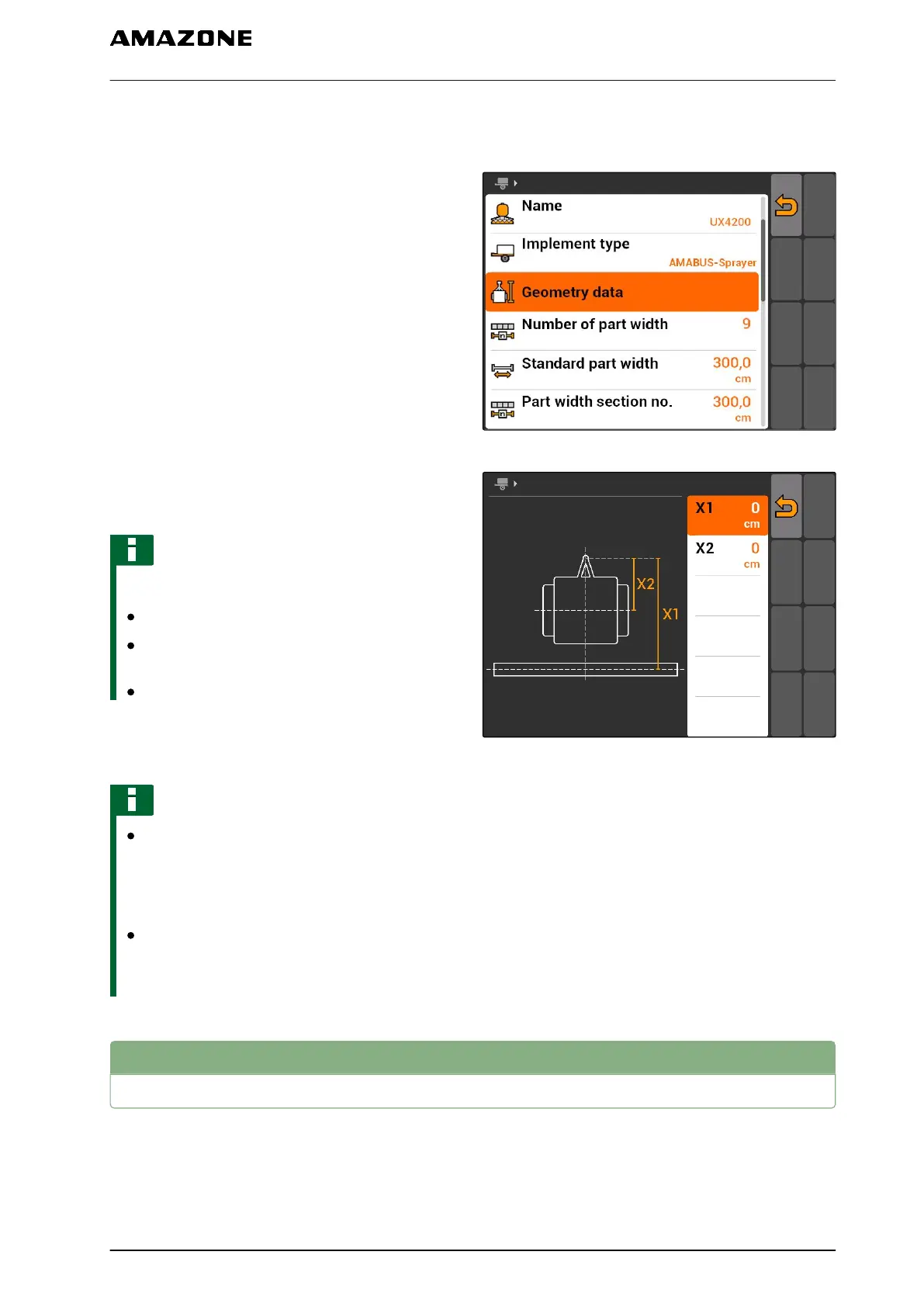
1. Select "Implement data" > "Geometry data".
CMS-I-002225
2. Under "X1", enter the distance between the
coupling point and the application point.
NOTE
Application points:
Field sprayers: Spray nozzles
Fertiliser spreaders: Centre point of the
spreading discs
Seed drills: Rear seeding coulters
3. Under "X2", enter the distance between the
coupling point and the axle.
NOTE
The value "X2" is only required for towed
implements. If "Towed" is selected for the
implement modelling in the GPS switch
settings, the value "X2" can be entered, see
page 79.
If the geometry values for a spreader are
changed, the headland distance must be
changed to the same value in the GPS switch
settings, see page 83.
CMS-I-001236
8.4
Selecting the implement
If one of the following implements is connected, this
connected implement must be selected to be able to
use GPS switch:
CMS-T-004824-A.1
8 | Configuring implements
Selecting the implement
MG5560-EN-II | E.1 | 21.04.2020
45
 Loading...