11.1.3 GPS quality requirements
GPS quality
DGPS
0 to 6 (nominal state) Good
HDOP 6 to 8 Medium
HDOP greater than 8 Poor
GPS
HDOP 0 to 6 Medium
HDOP 6 to 8 Poor
HDOP greater than 8 Poor
Good quality: Worked area is shown in green
Medium quality: Worked area is shown in yellow
Poor quality: GPS too imprecise. The field is no
longer displayed on the GPS switch.
11.2
Entering the basic settings for GPS switch
11.2.1
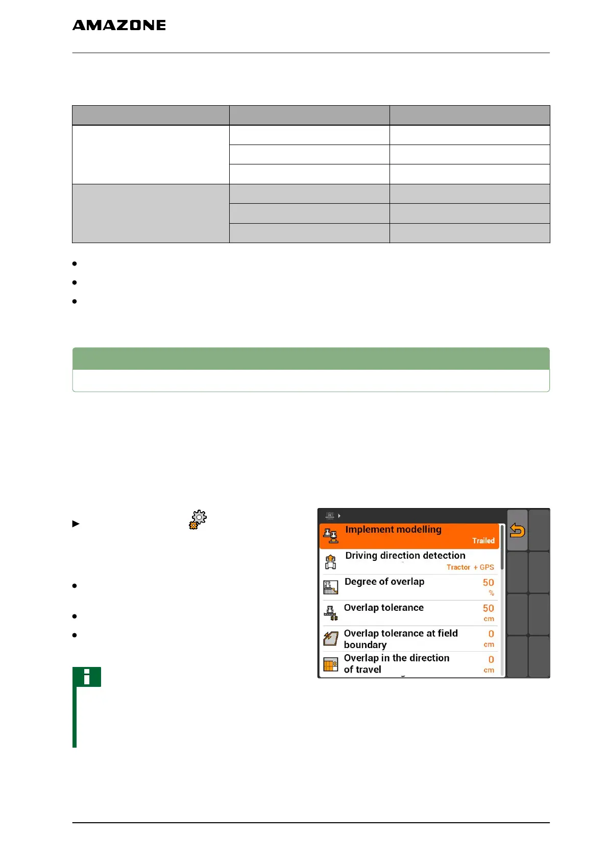
Defining the implement modelling
The specification of the implement modelling is
required to simulate the different following
characteristics of the implements.
Select "GPS switch" > > "Implement
modelling".
Possible settings:
"Mounted": For mounted implements and self-
propelled machines without four-wheel steering
"Towed": For implements with a drawbar
"Self-propelled machine": For self-propelled
machines with four-wheel steering
NOTE
If "Towed" is selected for the implement
modelling, the value "X2" must be entered for
AMABUS implements or manual implements in
the implement geometry data, see page 44.
CMS-I-001651
CMS-T-006650-A.1
CMS-T-00004680-A.1
CMS-T-003460-A.1
11 | Using the GPS switch
Entering the basic settings for GPS switch
MG5560-EN-II | E.1 | 21.04.2020
79