Installation and Setup
58
Enova Digital Media Switchers - Hardware Reference Manual
Audio Control and Signal Processing Options
Audio Switching Boards (ASB)
The audio signal on Audio Switching Boards can be switched independently of the video or as embedded audio. These
boards also allow for digital signal processing (e.g., volume, equalizer, input gain) on every input and every output in the
enclosure. When using Audio Switching Boards, the Enova DGX 6400 requires two each of the input and output boards for
functionality. Both boards are provided as part of the compatible DGX6400-ASB Audio Switching Board Kit for the Enova
DGX 6400.
NOTE: The Audio Insert/Extract Board has no control options aside from the configuration of DIP switches. All switching of
audio is executed in conjunction with the switches executed on the corresponding input and output connectors (for
additional information, see the Audio Insert/Extract Board chapter on page 175).
System Conf iguration Interface
Switching audio outputs/inputs – page 185
Switching a down-mixed signal – page 188
Configuring audio outputs/inputs – page 131
ICSP Commands
Switching audio outputs/inputs – page 209
Digital Signal Processing audio commands – page 225
Control Panel
NOTE: Audio from Audio Switching Boards cannot be switched independently from the Control Panel. When the audio
from the boards is embedded on a video signal, only volume, input gain, and mute can be applied from the Control
Panel.
Volume – page 75
Input gain – page 76
Mute – page 75
BCS Commands
Volume, input gain, and mute – See the BCS (Basic Control Structure) Protocol Programming Guide at
www.amx.com
.
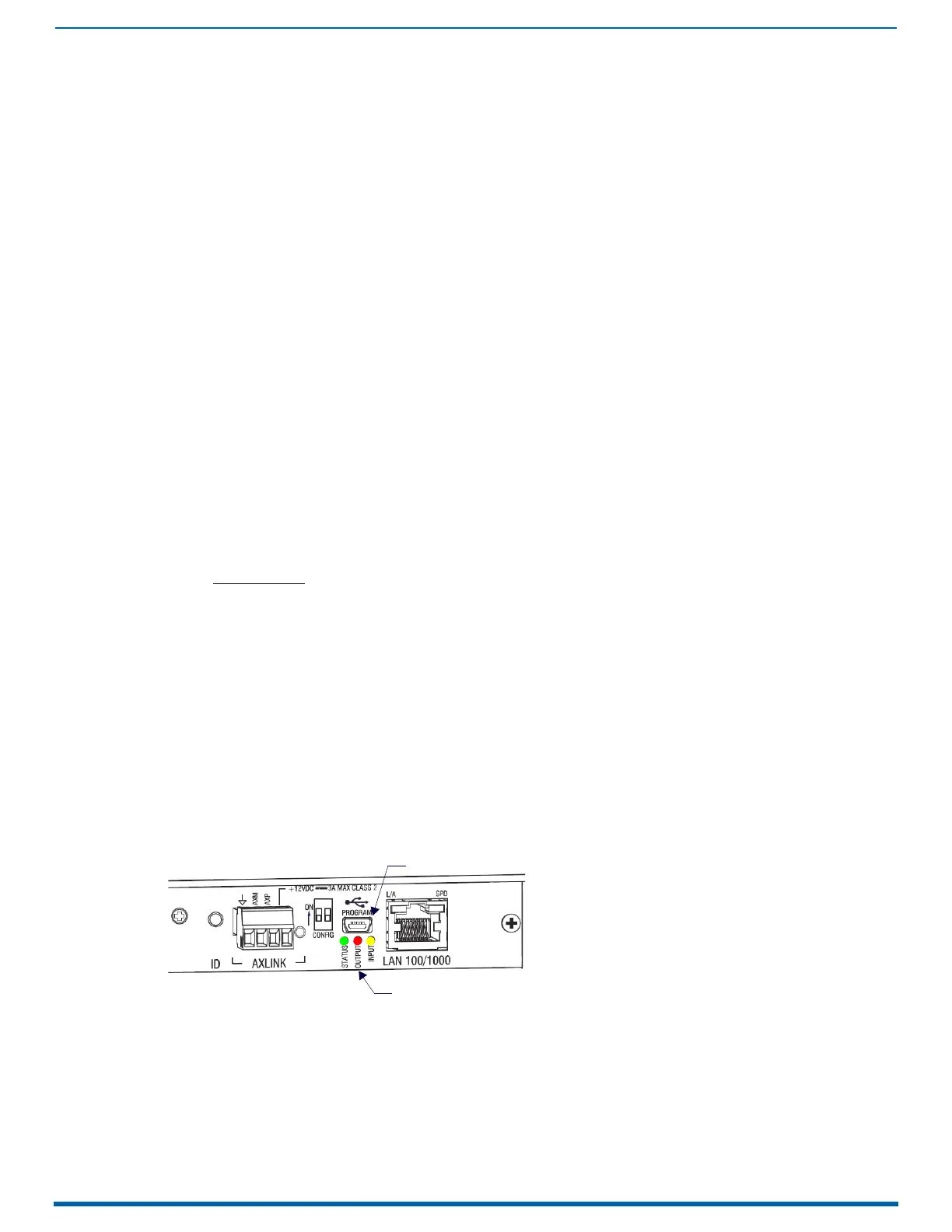
Establishing Serial Communication with a PC via the Program Port
Program Port
The Enova DGX Switcher’s integrated NetLinx NX Master is equipped with a low-speed USB connection labeled "Program."
Use the provided USB mini-AB adapter cable (CA1090-541) to establish a connection between the Program port on the
enclosure and the PC’s USB port.
This connection provides serial-based communication between the integrated Master and NetLinx Studio. This port is
useful for getting and setting the system’s IP address (in NetLinx Studio, open Tools/Telnet Session and enter either GET IP
<D:P:S> or SET IP <D:P:S>, where D:P:S is Device:Port:System).
IMPORTANT: The Program port is not recommended for firmware updates or large file transfers. These more data-intensive
operations are better handled via the LAN 100/1000 port connection.
Cable Requirements
USB mini-AB adapter cable (provided) – required to connect an Enova DGX Switcher via its Program port to a PC.
Program Port LEDs – Modes and LED Blink Patterns
FIG. 26
Program Port LEDs
PROGRAM Port LEDs
PROGRAM (USB) Port
 Loading...