CPU/Control Board (all DGX 100 Series Enclosures)
66
Enova Digital Media Switchers - Hardware Reference Manual
CPU/Control Board (all DGX 100 Series Enclosures)
Overview
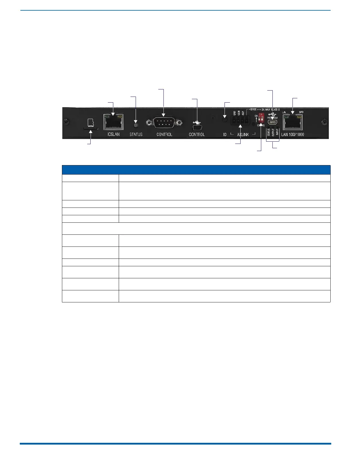
The CPU/Control board is identical for all DGX 100 Series Enclosures (FIG. 32). It is located on the left rear of the enclosure,
directly below the input connectors on the Enova DGX 800/1600/3200, and directly below the left bank of output
connectors on the Enova DGX 6400.
NOTE: For an overview of integrated NetLinx NX Master functionality, see page 28.
FIG. 32
DGX 6400 - Rear Panel Components
CPU/Control Board Components
SD card slot Ships with an installed MicroSD memory card for future functionality.
ICS LAN 10/100 port RJ-45 connector for communication with endpoint devices in auto-setup configuration over ICS LAN
(private network).
NOTE: Do not use for a TCP/IP connection or linking of enclosures.
System Status LED Indicates system status (see page 283)
Control port DB-9, RS-232 connector for attaching an external serial control device (see page 313).
Control port USB mini-B connector for attaching an external control device (see page 313).
NOTE: The Control ports provide direct control of matrix switcher processing. They do not work on the same layer of control as the
integrated NetLinx NX Master, which uses the LAN 100/1000 and Program ports.
ID Pushbutton For selecting static IP or DHCP, resetting the factory defaults, and restoring the factory firmware image (see
page 60).
AxLink port/Status LED 4-pin captive wire connector for supporting AMX AxLink devices. The LED to the right of the AxLink port
indicates AxLink data activity (see page 59).
Config DIP switch 2-position toggles for setting the Program Run Disable (PRD) mode (see page 61).
Program port USB mini-AB connector for establishing a connection from the integrated NetLinx NX Master to the PC’s
COM port (see page 58).
Communication Status
LEDs
Status, Output, and Input LEDs indicate system communication status and indicating when data is sent and
received (for modes and blink patterns, see page 58)
LAN 100/1000 port Ethernet RJ-45 port for connecting from the integrated NetLinx NX Master to a public LAN (see page 56) for
all runtime control, NetLinx programming, etc.
SD card slot
ICS LAN 10/100 port
System Status LED
DB-9 RS-232 serial Control port
USB mini-B
Control port
ID Pushbutton
AxLink port/Status LED
Configuration DIP switches
LAN 100/1000
port
USB mini-AB
Program port
Communication
Status LEDs
 Loading...