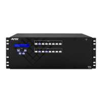
Control Panel
70
Enova Digital Media Switchers - Hardware Reference Manual
3. Type the labels in the preformatted cells on the template according to the instructions in the template (if desired, use
standard Excel editing tools to alter font size, spacing, color, etc.). Do not modify the cell size.
4. Save the file for future use (recommended).
5. Print the labels on the perforated sheets provided, using any standard laser printer.
6. Trim off the excess label insert material where indicated.
7. Separate the label strips at their perforations (bend back and forth first).
8. Slide the first label strip into a plastic label holder (position with open edge of holder up).
9. Peel the adhesive backing off the label holder and press the holder firmly onto the Control Panel above the
appropriate Input or Output keys. The silk screened labels on the front panel will aid in label holder alignment.
10. Repeat Steps 8 and 9 for the remaining labels.
Executing Switches
A switch is an active connection between an input (source) device and one or more output (destination) devices. The
signals routed in a switching operation are individual signals or groups of individual signals coming through the connectors
on the rear of an enclosure. You can execute switches from the Control Panel using the steps below or by defining and
executing a global preset (see page 72).
The LCD displays the VM (default VM 0) in the upper-right corner; this is the virtual matrix that operations are currently
being executed on. Switches are executed on the default virtual matrix unless otherwise specified. When specifying a
virtual matrix, be sure it includes the signal(s) you want to route.
Virtual matrix definitions reside in the configuration information in an enclosure’s CPU. If you need to change the virtual
matrix that switches are being executed on, see "Changing the Virtual Matrix" on page 71. If you decide to change the
default virtual matrix, see page 76 for "Setup Options."
In an execute switch command either an input or an output may be selected first. To switch to multiple outputs, the Input
key must
be selected first. Use the Control Panel to select and deselect Input and Output keys to modify the switch as
long as the keys are not flashing. Once satisfied with the switch selections, press the Take key to execute it. (Or, if not
satisfied with the selections, press the Cancel key and start over.)
For new installations, we recommend executing a test switch to verify the system is working correctly before attaching all
inputs and outputs. To execute a test switch, attach the first input (source) and first output (destination) and then
complete the directions below. For more information on test switches, see page 70.
Executing a Test Switch
The directions below switch Input 1 to Output 2 on VM 0.
NOTE: Before executing the test switch below, use the directions on page 71 to disconnect the factory default switch (i.e.,
disconnect Input 1 which is connected to all outputs on Virtual Matrix 1 when it leaves the factory).
1. Press the Function key. The Function menu appears.
2. Press the Select key to choose Change. The system is in Change Mode (the available Input and Output keys turn
blue).
3. Press Input key 1. Input key 1 flashes indicating that it is ready to switch (any outputs currently connected to a
selected input will turn white).
4. Press Output key 2. Output key 2 illuminates indicating that it is ready to accept the switch.
5. Press the Take key. Input 1 switches to Output 2, and the keys turn blue. The panel remains in Change Mode until the
Function key is pressed.
6. Press Input key 1 again to toggle it off, and Press the Take key to disconnect the test switch.
Controlling Switches on Systems with Audio Switching Boards
IMPORTANT:
The control panel does not have direct control of the audio signal on the Audio Switching Boards (ASB or ASB-DAN). The
analog audio signal from the Audio Switching Board must first replace the embedded audio on the HDMI signal via a
SEND_COMMAND (see page 225). Only then can the audio signal from the Audio Switching Board be switched with the video or routed
independently from the video as a breakaway.
Control of video and audio switching on systems with Audio Switching Boards (ASB or ASB-DAN) works as follows:
To switch digital video with its embedded audio, use either VM 0 (All) or VM 1 (Video).
To switch the embedded audio separately from the digital video (as a breakaway audio signal), use VM 2. When
switching on VM 0 or VM 1, the embedded audio is still present.
The embedded audio can also be analog audio from the Audio Switching Boards which has been used to replace the
embedded audio via a SEND_COMMAND (see page 225).

 Loading...