G3V4vs/R5vs/R6vs to Avaya Communication Manager
Task List: DEFINITY vs to Avaya Communication Manager
148 SI Installation and Upgrades
June 2004
10 Move the cabinet back into place.
11 Attach the cabinet to the front mounting angle using 4 No. 12-24 by 1/2-inch thread-forming
screws.
12 In the rear of the cabinet, lay the stiffener on the bottom of the cabinet aligning the stiffener with
the holes in the bottom of the cabinet.
13 Fasten the cabinet to the floor (Figure 4, Cabinet earthquake mounting — concrete floor, on page
149).
NOTE:
You install the earthquake front plate and earthquake ground plate later in the upgrade
procedure.
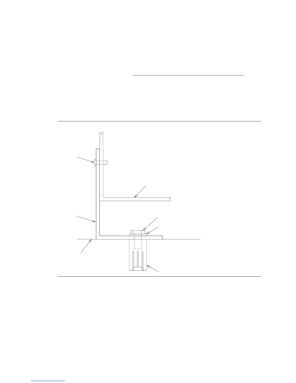
Figure 3: Front mounting angle — concrete floor
CABINET
3/8-16 X 1.25 BOLT (2 REQ’D)
THREAD-FORMING SCREW
CONCRETE ANCHOR
NYLON INSULATING WASHER
(2 REQ’D)
NO. 12-24 X 1/2 INCH
(4 REQ’D)
FRONT
MOUNTING
ANGLE
CONCRETE FLOOR
(2 REQ’D)
CABINET
3/8-16 X 1.25 BOLT (2 REQ’D)
THREAD-FORMING SCREW
CONCRETE ANCHOR
NYLON INSULATING WASHER
(2 REQ’D)
NO. 12-24 X 1/2 INCH
(4 REQ’D)
FRONT
MOUNTING
ANGLE
CONCRETE FLOOR



 To Next Page