Test the System
LED Indicators
SI Installation and Upgrades 487
June 2004
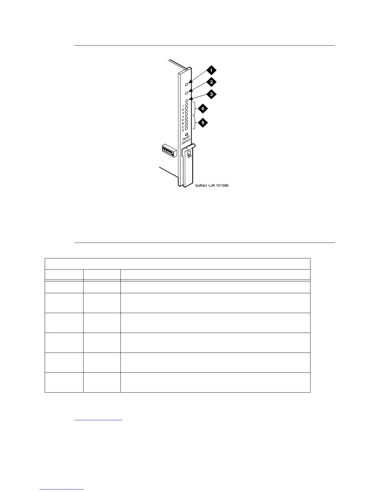
Figure 180: TN1654 DS1 Converter Circuit Pack LEDs
.
Check System Status for Each Cabinet
Return to Task List
The system status may suggest problem areas. Specific tests later provide more specific diagnostic
information.
Figure notes
1 Alarm LED (Red)
2 Test LED (Green)
3 Busy LED (Yellow)
4 STATUS LEDs
5 SPAN LEDs
DS1 Converter Yellow LED Flashing States
LED on LED off Condition
0.1 second 0.1 second Fiber out-of-frame or fiber loss of signal
0.5 second 0.5 second In frame, fiber channel down. The fiber channel communicating between
the DS1 Converter and the other fiber endpoint (EI or SNI) is down.
1 second 1 second In frame, control channel down. The control channel between the 2 DS1
Converters in the DS1 Converter complex is down.
2 seconds 0.2 second No response from SPE. The SPE is not acknowledging messages from
the DS1 Converter or the communications link to the SPE is down.
solid on DS1 Converter active. This is the normal state for an active DS1
Converter.
solid off DS1 Converter standby. This is the normal state for a standby DS1
Converter in critical reliability systems (duplicated PNC).