Option Switch Settings
Task List: Data Module Switches and Options
744 SI Installation and Upgrades
June 2004
Set DCS Switches
Return to Task List
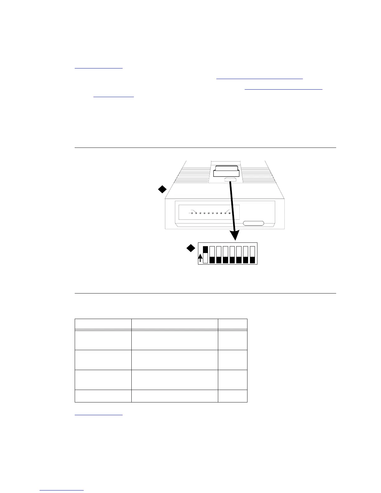
1 Remove the top cover from the data module. See Figure 296, DIP Switch Locations, on page 744.
2 Switches 1, 5, and 8 are the only switches to be set. Refer to Table 35, Data Module Option
Switch Settings, on page 744 for the option switch settings.
NOTE:
The options for the 7400A and 7400C Data Modules are set from the front panel interface.
For the 7400A, refer to 7400A Data Module User’s Guide (555-020-710). For the 7400C,
refer to DEFINITY® Communications System High Speed Link User’s Guide.
Figure 296: DIP Switch Locations
.
Return to Task List
Figure notes
1 Data Module (7400A Shown) 2 DIP Switch
Table 35: Data Module Option Switch Settings
DIP Switch Function Setting
1 With Phone
Without Phone
ON
OFF
5 Data Metering
No Data Metering
ON
OFF
8 Make Busy on Loc Loop
No Make Busy on Loc Loop
ON
OFF
2, 3, 4, 6, and 7 OFF
1
2
DTE
POWER
TEST
DATA
METERING
7400B Data M odule
AA CD RD SD TR OH
CHECK
SPEED
DATA
12345678
O
N