Install and Wire Telephones
Three-Pair and Four-Pair Modularity
514 SI Installation and Upgrades
June 2004
Three-Pair and Four-Pair Modularity
Return to Task List
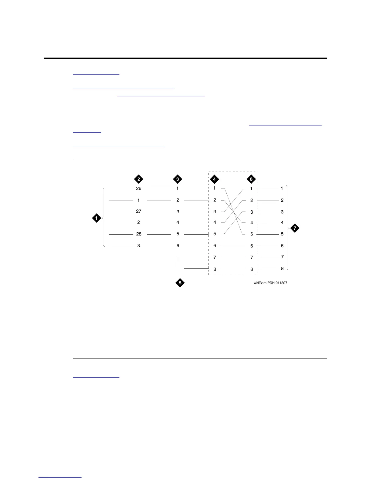
Figure 198, 3-Pair and 4-Pair Modularity, on page 514 is from the port circuit pack to the voice or data
terminal. Refer to Install Telecommunications Cabling
on page 403 for descriptions of 3- and 4-pair
modularity and distribution.
Most terminals connect to an information outlet (modular jack) installed at the work location. Make the
connections from the port circuit pack to the modular jacks, as shown in Figure 198, 3-Pair and 4-Pair
Modularity, on page 514. Then, plug the terminal into the modular jack.
Adjunct Power Connection Locations
on page 515 shows three methods of connecting adjunct power.
Figure 198: 3-Pair and 4-Pair Modularity
Return to Task List
Figure notes
1 Port Circuit Pack
2 System Cabinet Connector Pins
(3-Pair Modularity)
3 Main Distribution Frame (MDF)
Pins
(3-Pair Modularity)
4 Input to Information Outlet (4-
Pair Modularity)
5 Adjunct Power
6 Output From Information Outlet
(4-Pair Modularity)
7 Voice or Data Terminal Pins