Option Switch Settings
Call Detail Recording Option Settings
752 SI Installation and Upgrades
June 2004
Return to Task List
Call Detail Recording Option Settings
Return to Task List
The interface between the system and Call Detail Recording (CDR) equipment may be one of the
following:
• Data Module — Recommended option settings are shown in Options for D-Lead and Attention
Control Modems on page 753.
• Modem — Recommended option settings are in modem vendor document
• TN726B Data Line circuit pack and an Asynchronous Data Unit — Data modules or modems are
not required.
• Connected directly to the DCE connector (Electronic Industries Association [EIA] Port) located
on the rear of the Control Carrier —
Data modules or modems are not required.
A 572 Printer can be used as an output receiving device for Call Detail Recording (CDR). The
recommended option settings for this printer are shown in 572 Printer Used with Management Terminal,
CDR, and Journal Printer on page 753 and 572 Printer Used as System Printer on page 755. Also, a
TELESEER, Call Detail Recording (CDR), 94A Local Storage Unit (LSU), or Customer Premises
Equipment (CPE) can be used as the output receiving device.
Administration procedures for Call Detail Recording (CDR) equipment are provided in Administrator’s
Guide for Avaya Communication Manager (555-233-506).
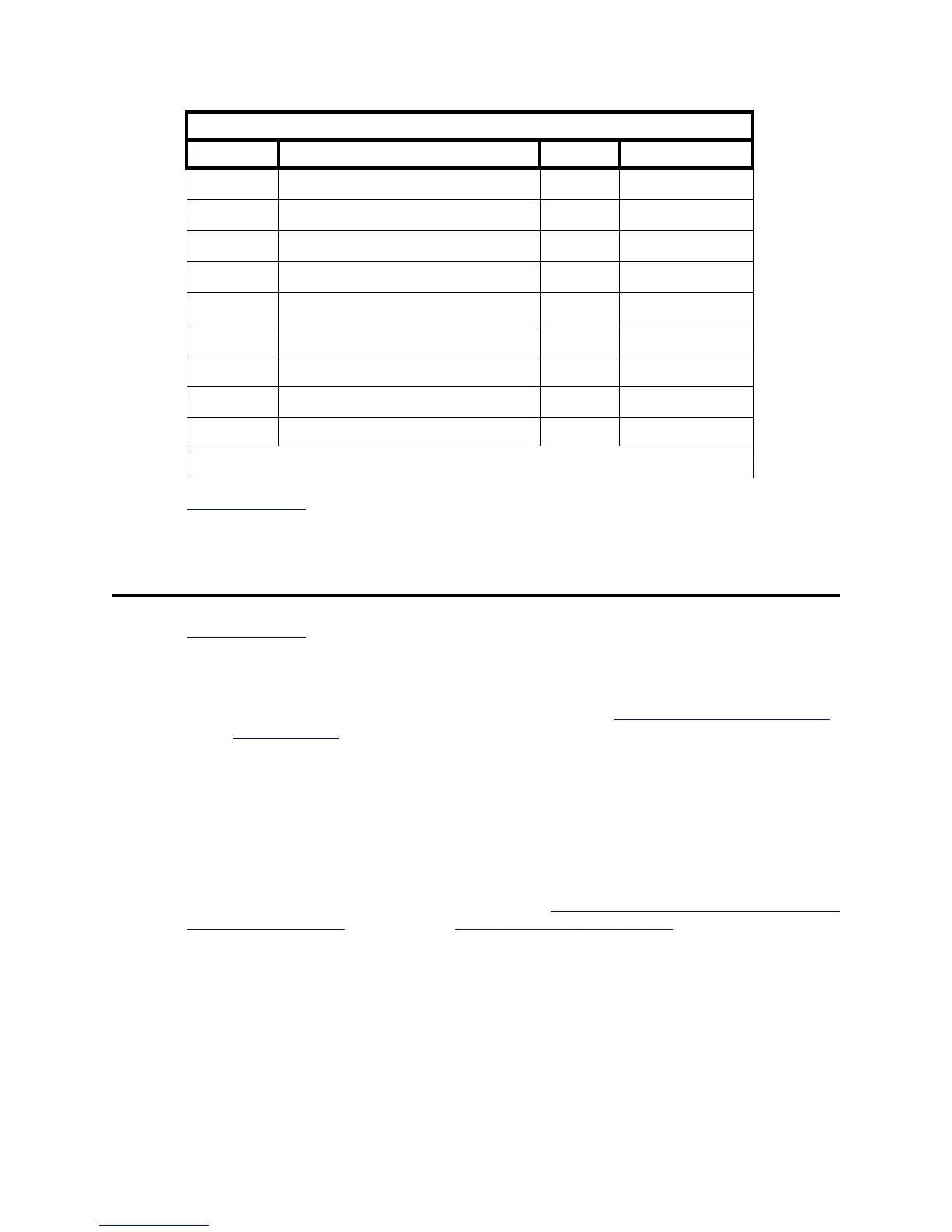
83 REQUEST TO SEND (RTS) TIMING 01 RTS
84 CD 02 OFF
85 CLEAR TO SEND (CTS) 02 OFF
91 OVER RUN 02 256
92 DATA BIT 02 8
93 PROTOCOL 03 XON/XOFF
94 STOP BIT 01 1
95 PARITY 01 NONE
96 PBS 04 1200
572 Printer Used as System Printer
Function Function Name Menu Menu Status
2 of 2