Install Telecommunications Cabling
Coupled Bonding Conductor
SI Installation and Upgrades 415
June 2004
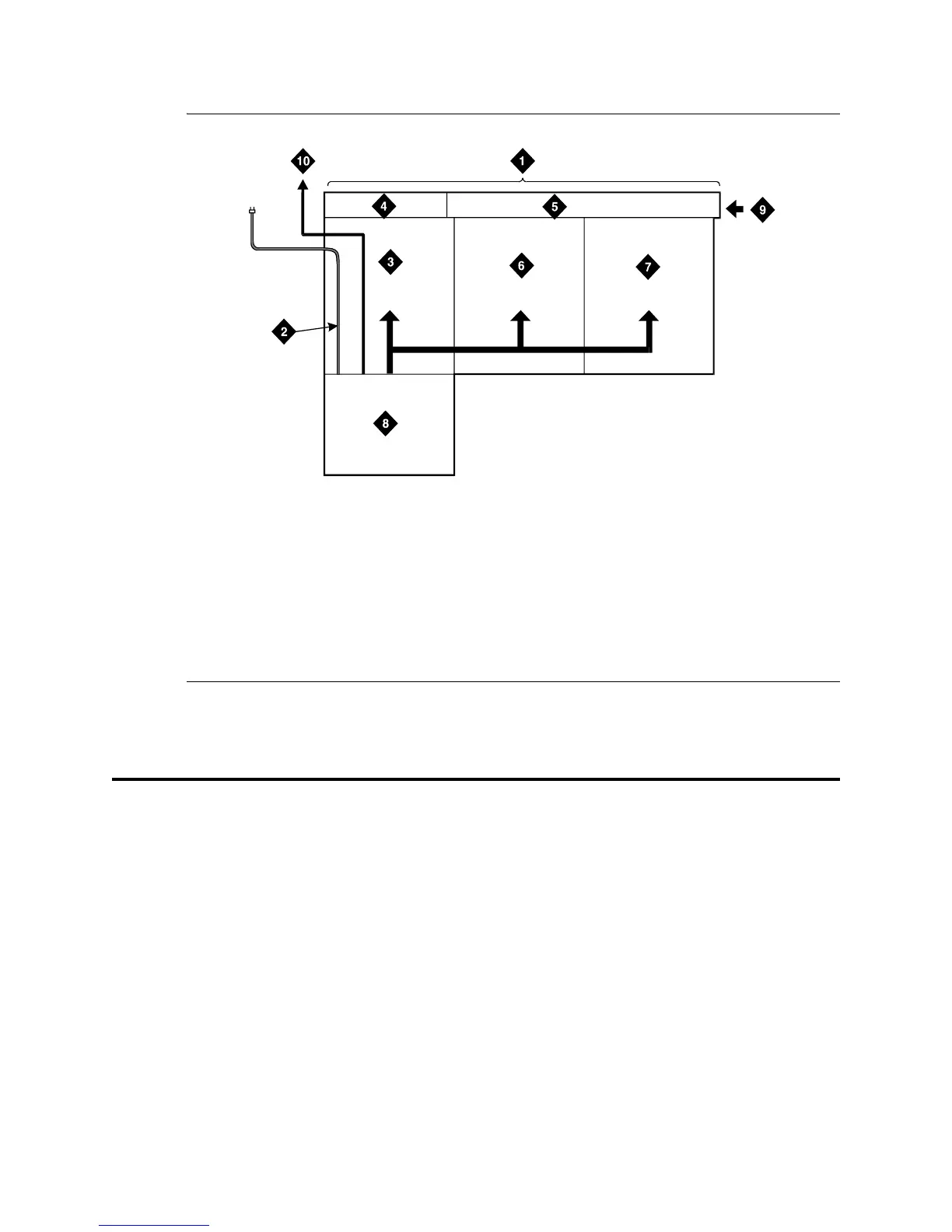
Figure 143: Cable Routing to Bottom Terminal Blocks
Coupled Bonding Conductor
The Coupled Bonding Conductor (CBC) connects to the single-point ground block and runs adjacent to
pairs in an associated telecommunications cable. The mutual coupling between the bonding conductor
and the pairs reduces potential differences in terminating equipment.
The conductor consists of a 10 AWG (#25) (2.5 mm
2
) wire tie-wrapped to the inside wiring cable and
terminated at the CBC terminal bar at the Main Distribution Frame (MDF). A minimum of 12 inches
(30.48 cm) spacing must be maintained between the CBC and other power and ground leads.
The 10 AWG (#25) (2.5 mm
2
) wire must be long enough to reach the telecommunications cables at the
rear of the system cabinets, follow these cables to the MDF, and to terminate at the CBC.
r758432b MMR 052996
Figure notes
1 Main Distribution Frame
2 AC Power Cord (AC-Powered
Cabinets Only)
3 Cable Slack Manager Number 1
4 Trunk/Auxiliary Field
5 Station Distribution Field
6 Cable Slack Manager Number 2
7 Cable Slack Manager Number 3
8 System Cabinet(s)
9 Building Cables (Through Cable
Trough)
10 10 AWG (#25) (6 mm
2
) Wire to
Coupled Bonding Conductor