System 75 XE to R8si (Blowback)
Task List: System 75 XE to R8si
SI Installation and Upgrades 265
June 2004
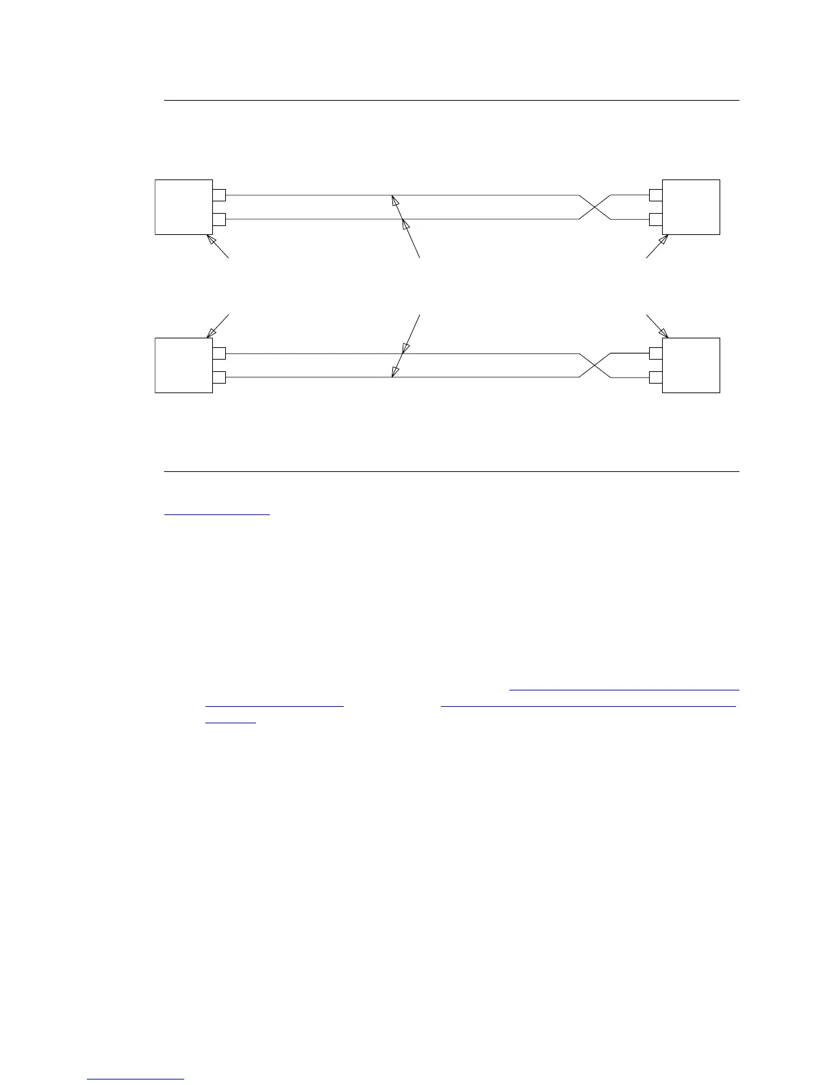
Figure 63: Critical Reliability fiber optic connections (adjacent cabinets)
Return to Task List
Connecting critical reliability remote cabinets
When a critical-reliability PPN and EPN are remotely separated with fiber, four fiber-optic cables (FL2P-
P-XX), four lightwave transceivers (9823-type), and four lightwave-interface units (provided by the
PSC) are required.
1 Behind control cabinet A of the single-carrier PPN (see Figure 64, Critical-Reliability Release 8si
with Two Port Networks, on page 267 and Figure 65, Critical Reliability fiber-optic connections
(remote), on page 268):
— Install a 9823-type lightwave transceiver on the connector at slot 1A01.
— Connect one end of a fiber-optic cable to the 9823-type lightwave transceiver at slot 1A01.
— Route the fiber-optic cable from the 9823-type lightwave transceiver to the cabinet cable
tray and out of the cabinet through the cable manager to the PDS cross-connect facility.
— At the PDS cross-connect facility, connect the fiber-optic cable to the lightwave-interface
unit provided.
— Delicately attach the fiber-optic cable (with cable ties) to the wall of the cable tray at the
built-in cable-tie positions.
TX
RX
2
3
1
RX
4
TX
1
2
3
4
EPN
TX
RX
RX
TX
PPN
PPN
CABINET A
LIGHTWAVE
TRANSCEIVERS
LIGHTWAVE
TRANSCEIVERS
EPN
CABINET B CABINET B
SLOT 1A01
CABINET A
SLOT 2A01
SLOT 1B01 SLOT 2B02
FIBER-OPTIC CABLES
9823-TYPE
FL2P-P-XX
9823-TYPE
 Loading...


