Install and Connect Modems
Task List: Install and Connect Modems
702 SI Installation and Upgrades
June 2004
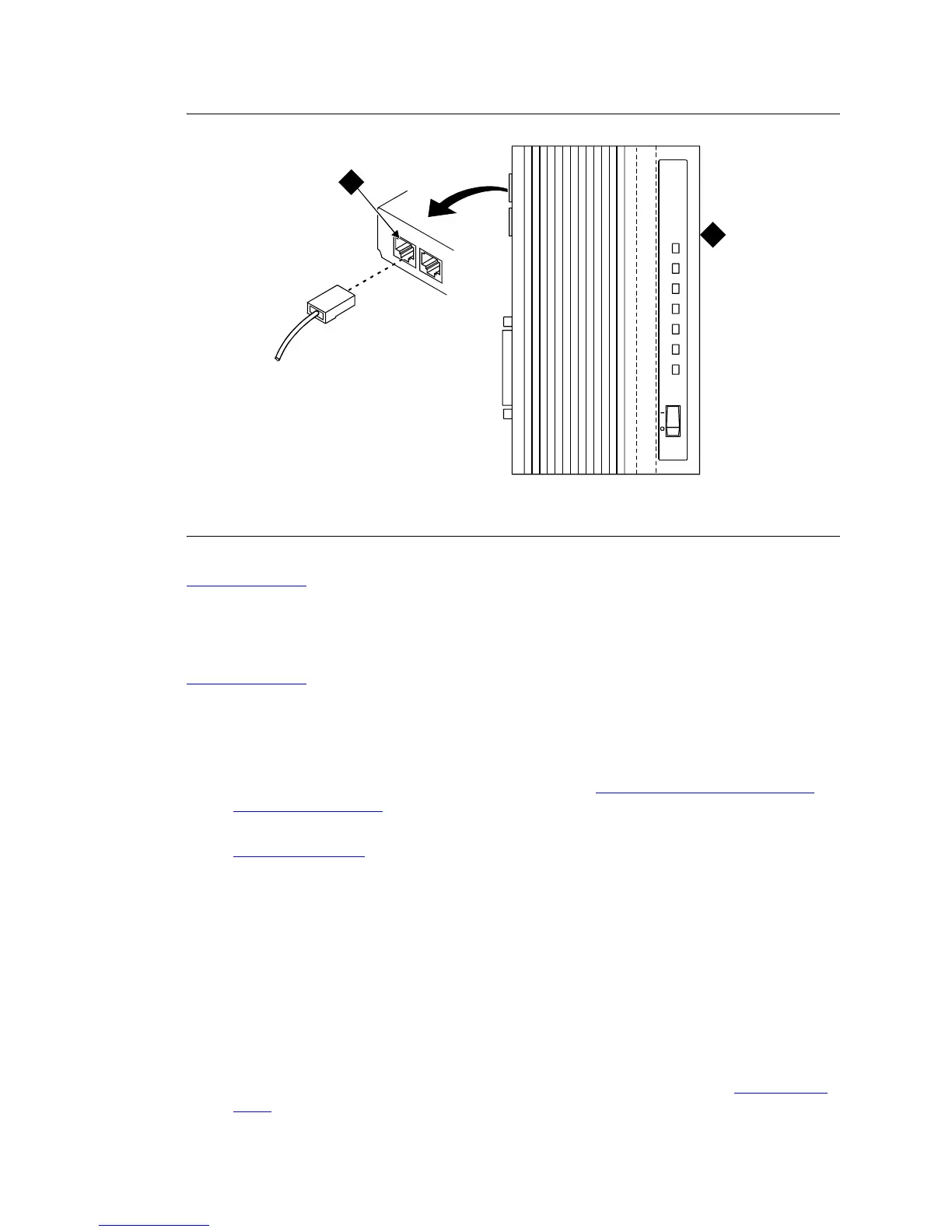
Figure 284: Network Jack on U.S. Robotics Modem
Return to Task List
Set External Modem Options
Return to Task List
A locally obtained, type-approved external modem may be used. Contact your Avaya representative for
information.
1 Set the modem switches:
• If a U.S. Robotics Model 839 modem is installed, refer to U.S. Robotics Model 839 External
Modem Switch Settings on page 703 to set the 8 option switches on the U.S. Robotics modem.
• If any other modem is installed, refer to the setup instructions provided with that modem. Refer to
SCC1 Modem Fields
on page 703 while setting up the modem.
2 At the management terminal, enter change system-parameters maintenance and press Enter.
3 Scroll to page 3 of the form. Set the Modem Connection: field to external if a modem is
installed. Set the field to none if no modem is installed.
NOTE:
This field must be administered or alarms will be generated. The Modem Connection:
field cannot be set to none if Alarm Origination is activated.
4 Set the Data Bits: field to 8 (default).
5 Set the Parity: field to none (default).
6 For non-United States installations, set the remaining modem fields as shown in SCC1 Modem
Fields on page 703.
Figure notes
1 Pin 1 of network jack 2 Modem
modmcabl KLC 110397
OFF ON
AA CD RD SD CS ARQ/FAXTR
Sportster
33.6
Faxmodem
1
2