Install Telecommunications Cabling
Cable Installation
414 SI Installation and Upgrades
June 2004
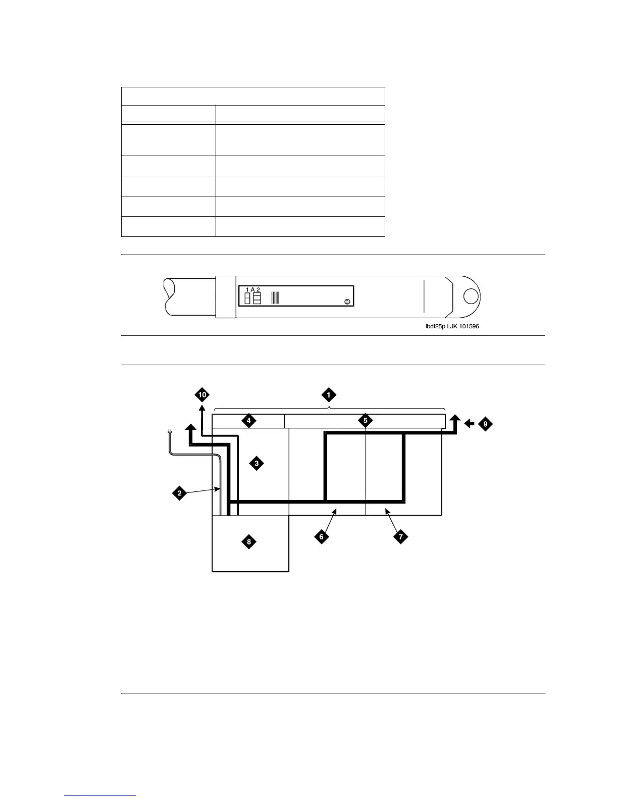
Figure 141: Self-Stick Label on 25-Pair Cable Connector
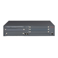
Figure 142: Cable Routing to Top Terminal Blocks
Equipment Room Labels
Label Name Range
Port Cable 1A1-1A20, 1B1-1B20, 1C1-1C20,
1D1-1D20, 1E1-1E20
Building Field Identified
Floor Field Identified
Auxiliary Cable Field Identified
Site or Satellite A-F and/or Field Identified
r758424b MMR 052996
Figure notes
1 Main Distribution Frame
2 AC Power Cord (AC-Powered
Cabinets Only)
3 Cable Slack Manager Number 1
4 Trunk/Auxiliary Field
5 Station Distribution Field
6 Cable Slack Manager Number 2
7 Cable Slack Manager Number 3
8 System Cabinet(s)
9 To Building Cables
10 10 AWG (#25) (6 mm
2
) Wire to
Coupled Bonding Conductor



 To Next Page