Test the System
LED Indicators
488 SI Installation and Upgrades
June 2004
1 If Multi-Carrier Cabinet (MCC1), type status system cabinet number <1-44> and press Enter.
or
If Single-Carrier Cabinet (SCC1), type
status system all-cabinets and press Enter.
2 Verify the screen displays system status screens similar to Figure 181, Sample System Status
Screen for Cabinet 1 (Page 1 of 3), on page 488 and to Figure 182, Sample System Status Screen
for Cabinet 2 (Page 2 of 3), on page 489.
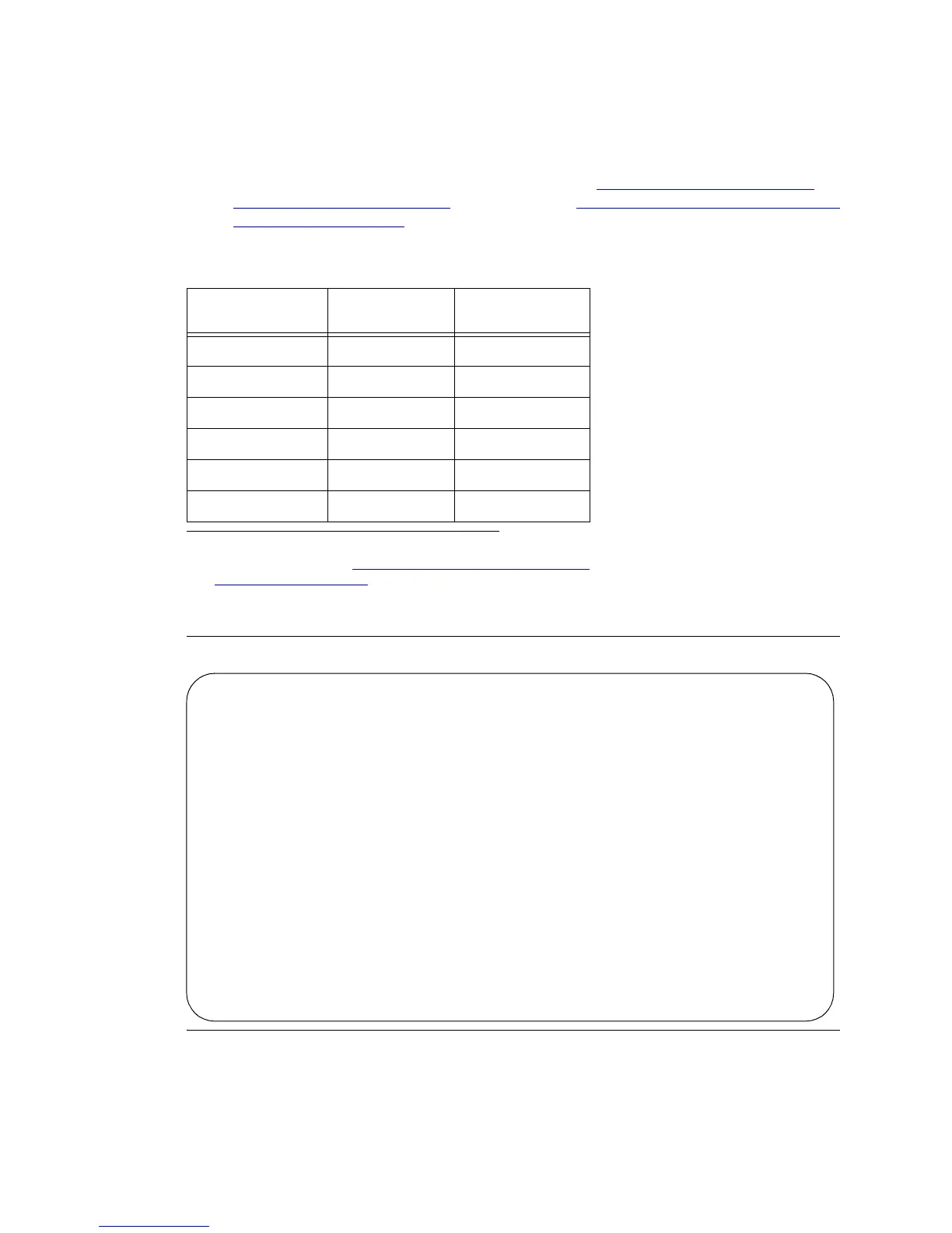
Verify these service states:
Figure 181: Sample System Status Screen for Cabinet 1 (Page 1 of 3)
Screen
page/section Field
Service
State
Page 1, section 1 Tone/Clock in
Page 1, section 2 TDM in
Page 1, section 3 EXP-LINK
*
* The cabinet/carrier/slot numbers for the fiber optic cables are listed.
For example, 01A01 in Figure 181, Sample System Status Screen
for Cabinet 1 (Page 1 of 3), on page 488 refers to cabinet stack 01,
carrier A, and slot 01.
in
Page 2, section 1 Tone/Clock in (for Cabinet 2)
Page 2, section 2 TDM in (for Cabinet 2)
Page 2, section 3 EXP-LINK* in (for Cabinet 2)
status system all-cabinets Page 1 of 3 SPE A
SYSTEM STATUS CABINET 1
SELECT SPE ALARMS TONE/ SERVICE SYSTEM SYSTEM
SPE MODE SWITCH MAJOR MINOR CLOCK STATE CLOCK TONE
1A active auto 0 0 1A in standby standby
1B maint/init auto 0 0 1B in active active
SERVICE CONTROL DEDICATED SERVICE BUS ALARMS BUS OPEN BUS
TDM STATE CHANNEL TONES PKT STATE MAJOR MINOR FAULTS LEADS
1A in y n 1 in
1B in n y
EMERGENCY SELECT SERVICE CABINET
TRANSFER SWITCH EXP-LINK STATE MODE TYPE
1A auto-on 01A01-02A01 in standby SCC
1B auto-on 01B01-02B02 in active