System 75 XE to R8si (Blowback)
Task List: System 75 XE to R8si
SI Installation and Upgrades 259
June 2004
— Install a 9823-type lightwave transceiver on the connector at slot 1A01.
— Connect one end of the fiber-optic cable to the 9823-type lightwave transceiver at slot
1A01.
— Route the fiber-optic cable from the 9823-type lightwave transceiver to the cabinet’s cable
tray and downward out of the cabinet to the EPN stack.
2 Behind control cabinet A of the single-carrier EPN:
— Install the same kind (either 9823-A or 9823-B) of lightwave transceiver on cable
connector at slot 2A01.
— Connect the other end of the fiber-optic cable, coming from the PPN, to the 9823-type
lightwave transceiver at slot 2A01.
3 Carefully attach the fiber-optic cable (with cable ties) to the rear covers of the EPN stack.
4 Coil up the surplus length of fiber-optic cable, and place the coil either in the cable manager or on
the bottom shelf (holding the power supply) of the PPN cabinet.
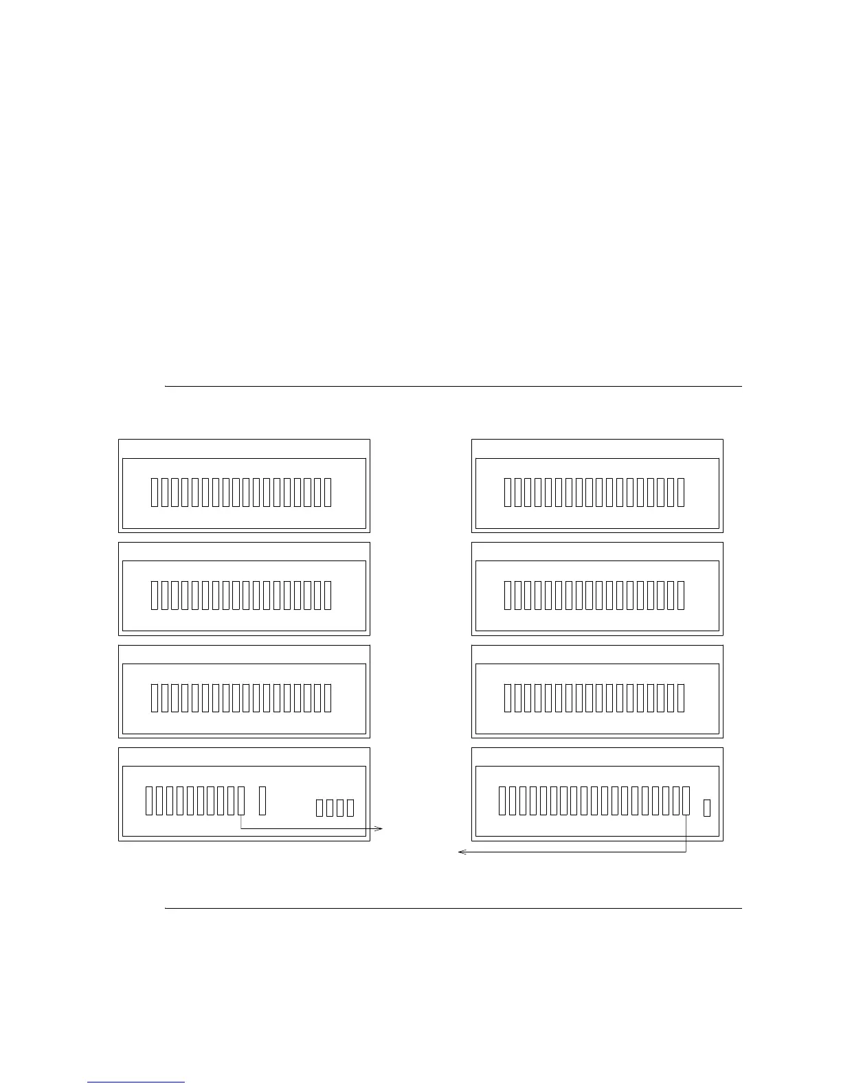
Figure 58: Standard-Reliability Release 8si with Two Port Networks
Rear View
Cabinet Stack 1
PPN
D
Port Cabinet - J58890H
18 17 16 15 14 13 12 11 10 9 8 7 6 5 4 3 2 1
C
Port Cabinet - J58890H
18 17 16 15 14 13 12 11 10 9 8 7 6 5 4 3 2 1
B
Port Cabinet - J58890H
18 17 16 15 14 13 12 11 10 9 8 7 6 5 4 3 2 1
A
Control Cabinet - J58890L
10 9 8 7 6 5 4 3 2 1
To Cabinet 2
A1
AUX
Terminal
Rear View
Cabinet Stack 2
EPN
D
Port Cabinet - J58890H
18 17 16 15 14 13 12 11 10 9 8 7 6 5 4 3 2 1
C
Port Cabinet - J58890H
18 17 16 15 14 13 12 11 10 9 8 7 6 5 4 3 2 1
B
Port Cabinet - J58890H
18 17 16 15 14 13 12 11 10 9 8 7 6 5 4 3 2 1
A
Expansion Control Cabinet - J58890N
AUX 18 17 16 15 14 13 12 11 10 9 8 7 6 5 4 3 2 1
To Cabinet 1
A1
TERM