Install Telecommunications Cabling
Station Circuit Distribution from Equipment Room
424 SI Installation and Upgrades
June 2004
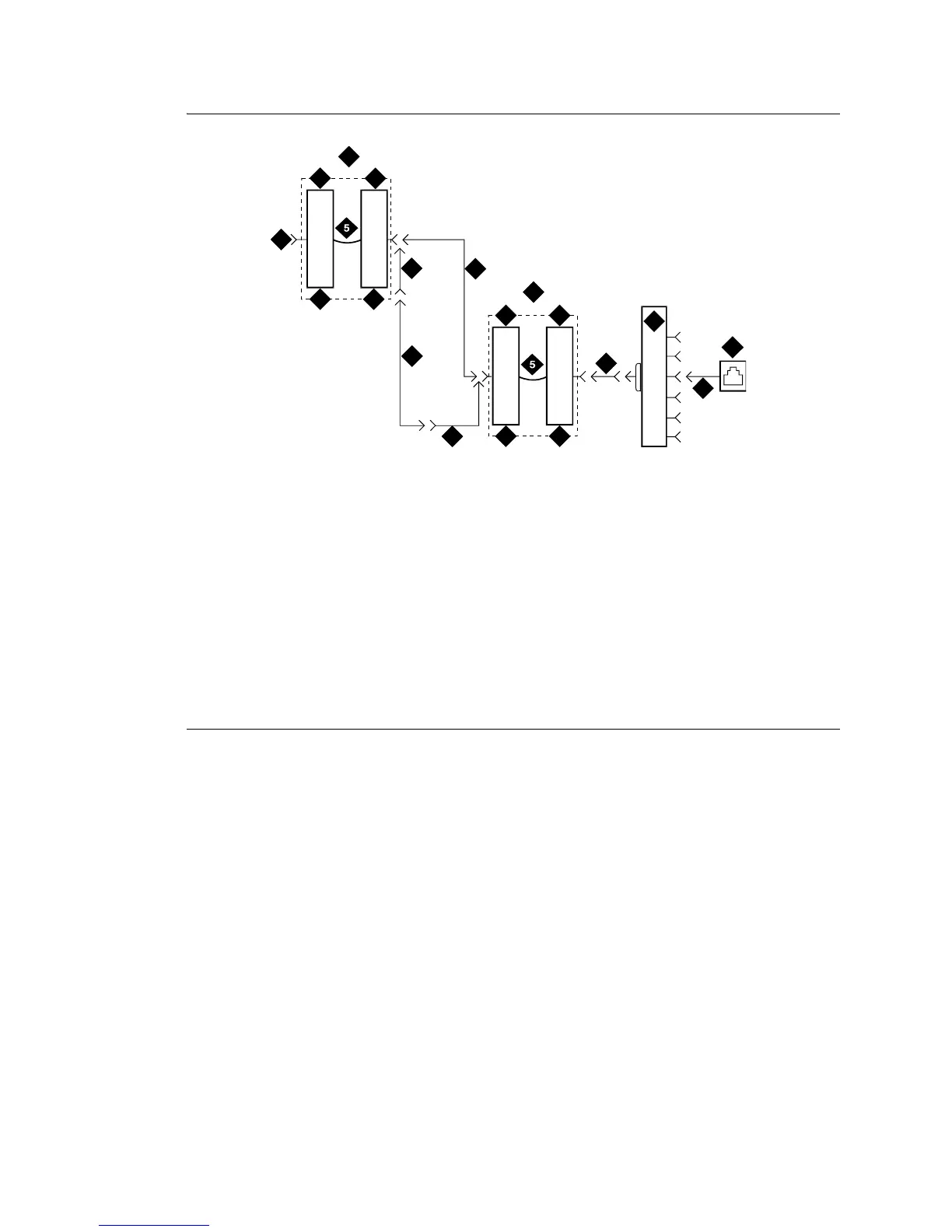
Figure 150: 3-Pair to 4-Pair Satellite Location Connectivity
2
2
3
8
8
4
4
9
10
3
11
7
6
1
12
16
15
14
13
Figure notes
1 Part of MDF
2 3-Pair Connecting Blocks
3 Purple Field
4 White Field
5 Patch Cord or Cross-Connect
Jumpers
6 To System Cabinet (3 Pair
Modularity)
7 A25D Cable (3-Pair Circuits)
8 B25A Cable
9 Connectorized (staggered finger) Multiple
25-Pair Cable
10 4-Pair Connecting Blocks
11 Blue Field
12 258A or BR2580A Adapter
13 Information Outlet
14 4-Pair Circuit [DIW Station Cable (D-
Inside Wire)]
15 Part of Satellite Location
16 4-Pair Circuits (B25A Cable)



 To Next Page