Bring the System Online
Task List: Make Data Module Settings
458 SI Installation and Upgrades
June 2004
Return to Task List
Set the Data Module to DCE Mode
Return to Task List
1 Cycle the power to the data module.
The unit performs a self test and displays its operating mode. Observe the display.
If the display reads DCE mode, proceed to Add a Data Module to the Switch
on page 458.
2 If the display reads DTE mode, reverse the mode select circuit board:
Remove the power cord from the unit, remove the cover from the top rear of the unit, remove the
mode select circuit board and turn it around, replace the cover, and connect the power cord.
The unit performs a self test.
NOTE:
The power LED must be steady on. If the power LED is blinking, the data module is not
communicating with the Avaya Media Gateway. Check the wiring at the MDF, wall jacks,
and data module.
Return to Task List
Add a Data Module to the Switch
Return to Task List
1 Add the data module administratively to the switch by typing add data-module number or add
data-module
next and pressing Enter.
2 In the Type: field, type pdm and press Enter.
3 In the Port: field, type the location of the digital line circuit pack connected to the data module
(for example 01A1503).
4 If system access ports and hunt groups have not been set up, set them up.
Refer to the Administrator’s Guide for Avaya Communication Manager (555-233-506).
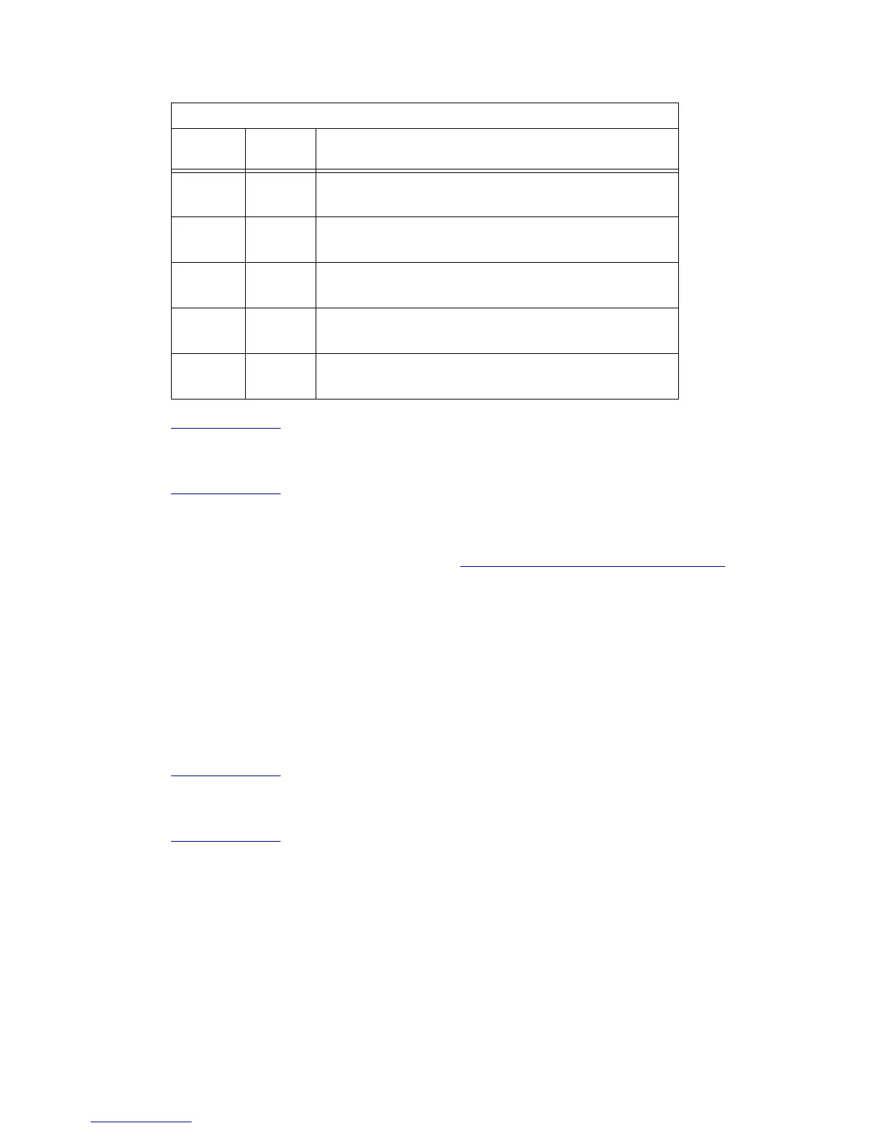
4UP
DOWN
Echo offline commands
No echo, offline commands
5UP
DOWN
Auto answer on first ring or higher if specified in NVRAM
Auto answer off
6UP
DOWN
Carrier detect normal
Carrier detect override
7UP
DOWN
Load NVRAM defaults
Load factory defaults
8UP
DOWN
Dumb mode
Smart mode
U.S. Robotics Modem DIP Switch Settings
Dip
Switch Setting Description
 Loading...


