Install and Wire Telephones
Task List: Typical Emergency Transfer Panel and Telephone Installation
SI Installation and Upgrades 547
June 2004
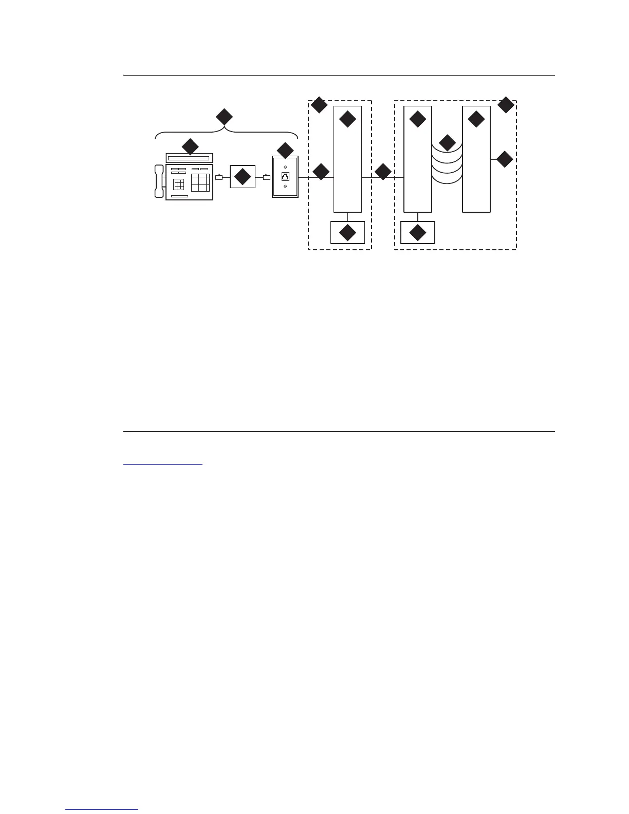
Figure 217: Example Adjunct Power Connections
Return to Task List
Figure notes
1 Typical Display Telephone
2 Individual Power Supply (Such as
1151A1 or 1151A2)
3 Information Outlet (Modular Jack)
4 4-Pair D-Inside Wire (DIW) Cable
5 Satellite Site or Adapter Location
6 25-Pair D-Inside Wire (DIW) Cable
7 Station Side of Main Distribution
Frame (MDF)
8 100P6A Patch Cord or Jumpers
9 System Side of Main Distribution
Frame (MDF)
10 25-Pair Cable to System Cabinet
(Analog Line Circuit Pack)
11 Equipment Room
12 Satellite Location
13 Work Location
14 Bulk Power Supply (Such as 1145B)
cydfadjn KLC 020599
1
2
3
4
5
6
7
8
9
10
1112
13
14 14
 Loading...


