Add Channel Service Units
Installing the 120A3A CSU
SI Installation and Upgrades 653
June 2004
7 If using external alarm equipment, attach the supplied DW8 cable to the 120A3A and the external
equipment. The maximum length of this cable depends on the alarm equipment.
8 If a TN464F is used, make sure the circuit pack is set for 24-channel operation. Set the switch on
the circuit pack.
9 From the DS1 circuit-pack form of the system administration console, set the line compensation
field to 0-133 feet (40.6 m).
10 Reset the 120A3A by reseating the DS1 circuit pack.
When you reinsert the DS1 circuit pack after installing a 120A3A CSU the 120A3A resets. The
DS1 circuit pack initializes and tests the 120A3A. When initialization and testing is complete, the
green LED goes off. If the RED indicator is OFF after the test, the ICSU is working.
11 If the circuits do not pass the self test, troubleshoot the 120A3A as instructed in Integrated CSU
Module Installation and Operation (555-230-193).
H700-383 Cable Pin Assignments
on page 654 provides the H700-383 cable pinouts. H700-383 Cable
Lengths by Group Number on page 654 provides the cable lengths for each cable group number.
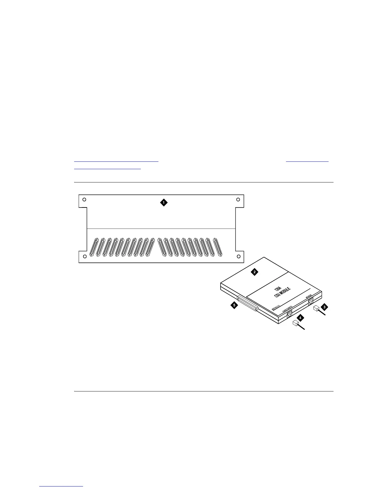
Figure 260: 120A3A Channel Service Unit Module
Figure notes
1 Rear of carrier containing DS1 circuit
pack
2 120A3A CSU
3 4-pair cord to network interface
(H700-383)
4 DW8A-DE 4-pair cord to alarm
contacts (optional)
5 To 25-pair connector on rear of carrier
containing DS1 circuit pack
16171819 15 14 13 12 11 10 09 08 07 06 05 04 03 02 01 AUX
icsupic RBP 032896