4. DLP System General Description
4.2 The DM D Device
DMD Device
Image 4-2
At the heart of every DLP™ p rojection system is an optical semiconductor known as the Digital Micromirror D evice, or DM D chip,
which was invented by Dr. Larry Hornbeck of Texas Instruments in 1987.
The DMD ch ip is probably the world’s most sophisticated light switch. It contains a rectangular array of hinge- mounted mic roscopic
mirrors, ea ch measuring less than one-fifth the width of a human hair, and corresponding to one pixel in a projected image.
When a DMD chip is coordinated with a digital video or graphic signal, a light source, and a projection lens, its mirrors can reflect an
all-digital image onto a screen or other surface. T he DM D and the sophisticated electronics that surround it are what we call Digital
Light Processing™ technology.
The F 90 D MD c hip is part of the Texas Instrument DLP9000 family and features over 4 million m icrom irrors on each c hip, offering a
dazzling high resolution 2560 x 1600 (WQX G A) array.
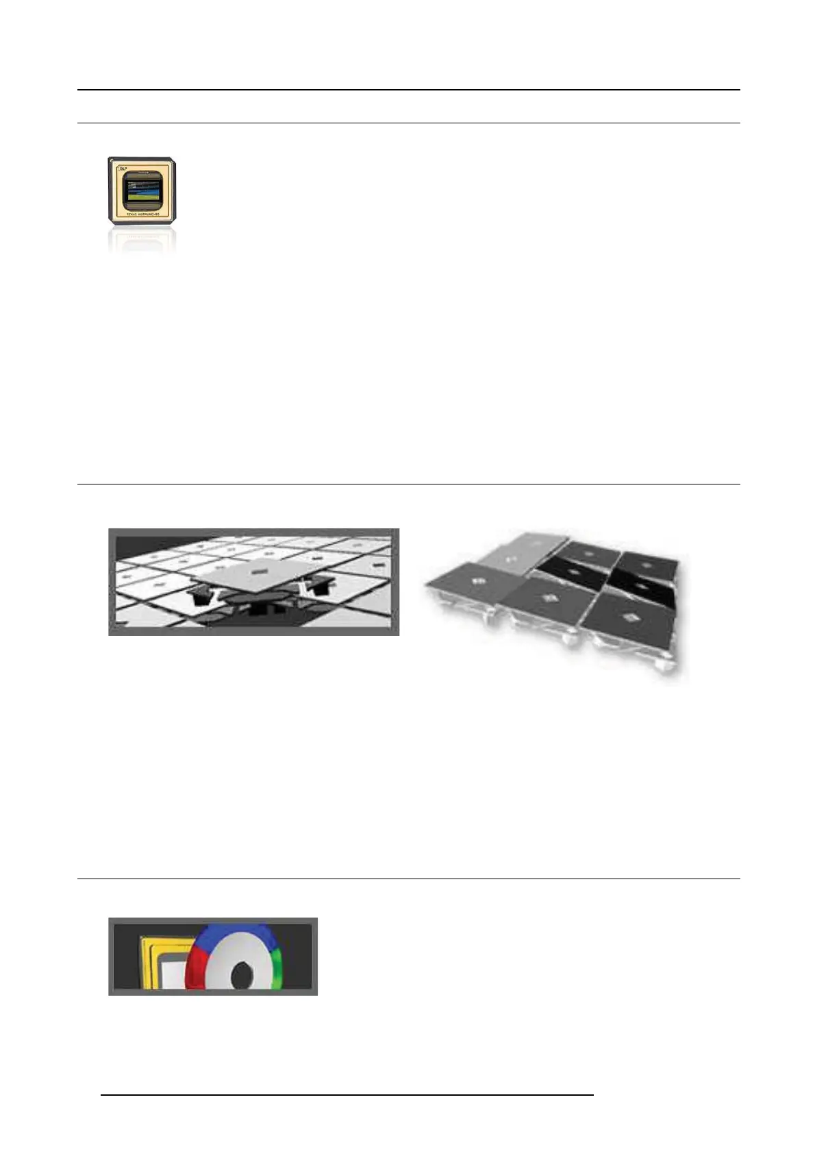
4.3 The Grayscale image
Grayscale
Image 4-3
Image 4-4
A DM D panel’s micro-mirrors are mounted on tiny hinges that enable them to tilt either toward the light s ource in a DLP™ projection
system (ON) or away from it (OFF)-creating a light or dark pixel on the projection surface.
The bit-streamed image code entering the semiconductor directs each mirror to switch on and off up to several thousand times
per second. W hen a mirror is switched on more frequently than off, it reflects a light grey pixel; a mirror that’s switched off more
frequently reflects a darker g rey pixel.
Inthisway,themirrorsinaDLP™projectionsystemcanreflect pixels in up to 1,024 shades of grey to convert the video or graphic
signal entering the DM D into a highly detailed gr ayscale image.
4.4 Adding C olor
Adding color
Image 4-5
The on and off states of each mic ro mirror on the DMD c hip are coordinated w ith the three basic building blocks of color – Red,
Green & Blue (RGB ). For example, a mirror responsible for projecting a pu rple pixel will only reflect red and blue light to the projection
surface. The switching of the mirrors and the proportion of time they are ’on’ or ’off’ is c oordinated according to the color shining on
14
723–0016 F90 01/12/2017