20. Scheduled operations
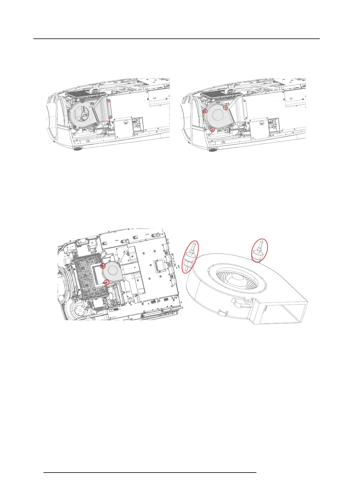
2. Remove 2 screws (Tx10 M3x6) securing the f an assembly to FE PSU. Remove the whole P SU fan assembly from the unit.
3. To release the fan from the air duc t, r emove 3 s crews (Tx10 M3 x10), and separate the fan from the duc t.
Note: Step 2 is not mandatory in order to remove the single fan, but recomm ended if you also plan to change FAN Optics
mounted.
Image 20-10
Removal of the complete assembly incl. the air duct
Image 20-11
Removal of the fan
20.2.4.2 Fan PCB
1. Disconnect the fan cable from the PCB thermal hub connector J26.
2. Disconnect the large brown LVDS flex cable on the PCB thermal hub side.
3. The f an PCB is m ounted in a rubber frame under the PCB and held in place with two rubber bumpers ( straps). Pu ll the restraints
up and out to release the fan.
Note: This procedure may be ea sier if you first remove the top bracket covering the PCB Thermal hub .
Image 20-12
Image 20-13
4. Install new rubber bumpers (511–0099–xx 390 Strap blower ) on the new fan.
5. Reinstall the fan.
20.2.4.3 Fan Optics
1. 1. Disconnect the fan cable from the PCB thermal hub, connector J35.
2. 2. Rem ove three screws (Tx10 M3 x10) from the fan house.
3. 3. Lift out the fan housing.
90
723–0016 F90 01/12/2017