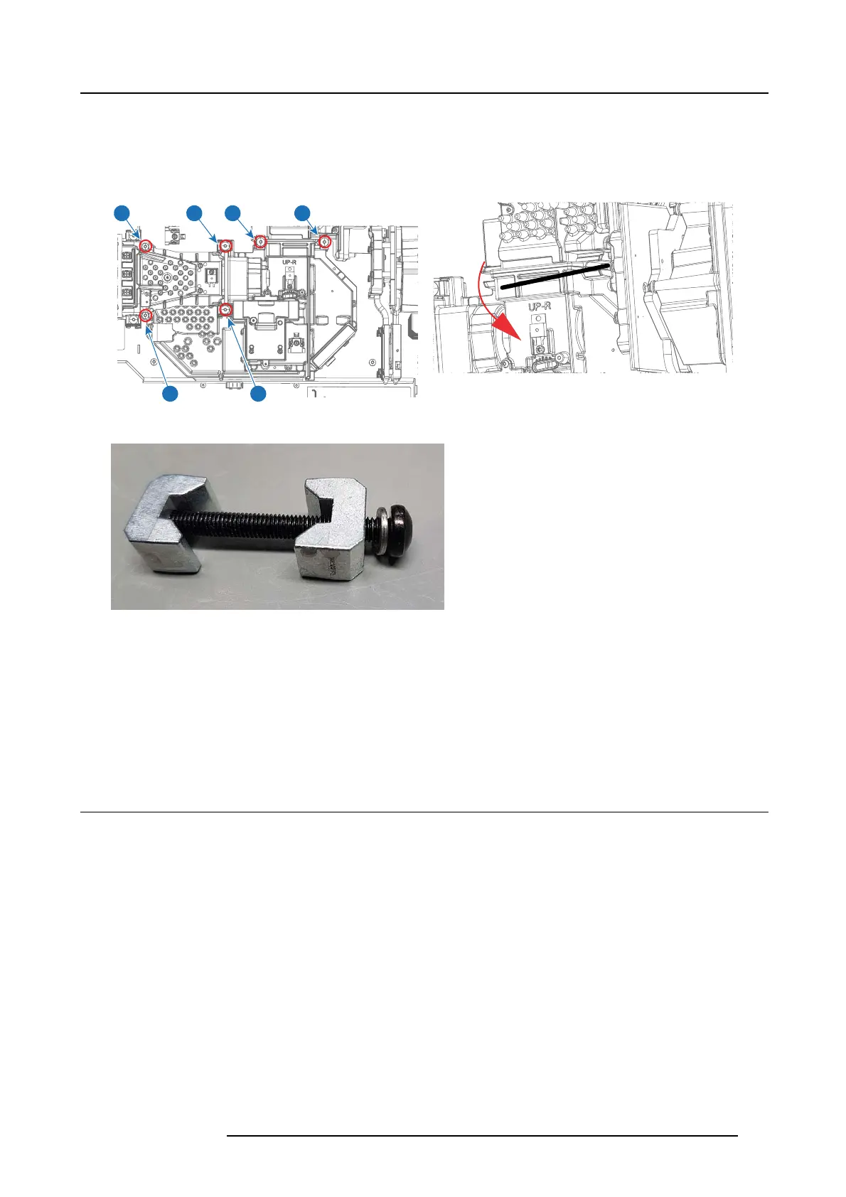
22. TI Loop
1. Remove 2 s crews securing the right laser interface to base plate.
2. Disconnect Laser Interface including Laser Cluster from the TI Loop by removing 2 screws (TX20 mM50X45) a nd Dow Tail clamps
(no need to open fully).
3. Release two screws (TX20 m5 0X45) opening the Dow Tail clamp s. This releases the TI loop from the Illumination E ngine Front.
1
1
2
3
2
3
Image 22-20
Image 22-21
Image 22-22
4. Lift up and out the complete right light path including the Phosp hor wheel compartment which you now have to separate from
the light path
5. Turn the TI Loop ups ide down, open the lid of the phos
phor wheel com partment
6. Remove the air guide to access screws below.
7. Release 3 screws securing phos phor wheel to access 2 new screws below.
8. Remove 3 screws (TX8
22.4 Rod Carrier Assy
The Rod Carrier Assembly is mounted inside the Illumination engine front and is a Dual R od system which merges the light from the
two illumination paths into a single seamless feed. It is recommended that you remove Color whe el p rior to removing the rod carrier
assemb ly.
1. Remove 3 sc rews (Tx08 M2 .5x6) and lift off Illumination engine c over.
2. Remove 3 screws (Tx8 M25x10) securing rod assembly to Illumination engine Front.
3. Carefully lift out rod a ssembly holding hollow rod.
723–0016 F90 01/12/2017
117