5. GP6 system functional description
5.7 Laser driver Principle and error codes
There are two identical las er driver PCB ’s, defined as Board 1 and Board 0, where Board 0 is the lower board and Board 1 is the
upper board.
There are also two identical laser clusters, de fined as C luster left and Cluster right, seen from the back s ide of the projector.
Each cluster again c onsists of six laser banks, defined as Bank0 to Bank5.
For m onitoring th e status/condition of the laser driver module, there are NTC’s connected to each laser bank and on each driver
output on the laser driver boards. The software will monitor the data from this NTC’s continuously and by an error, a failure message
will oc cur defining the error.
The NTC’s on the Laser driver board are defines as “heatsink” in the error message string, and the NTC ’s on the laser banks is
defined as “bank” in the error message string.
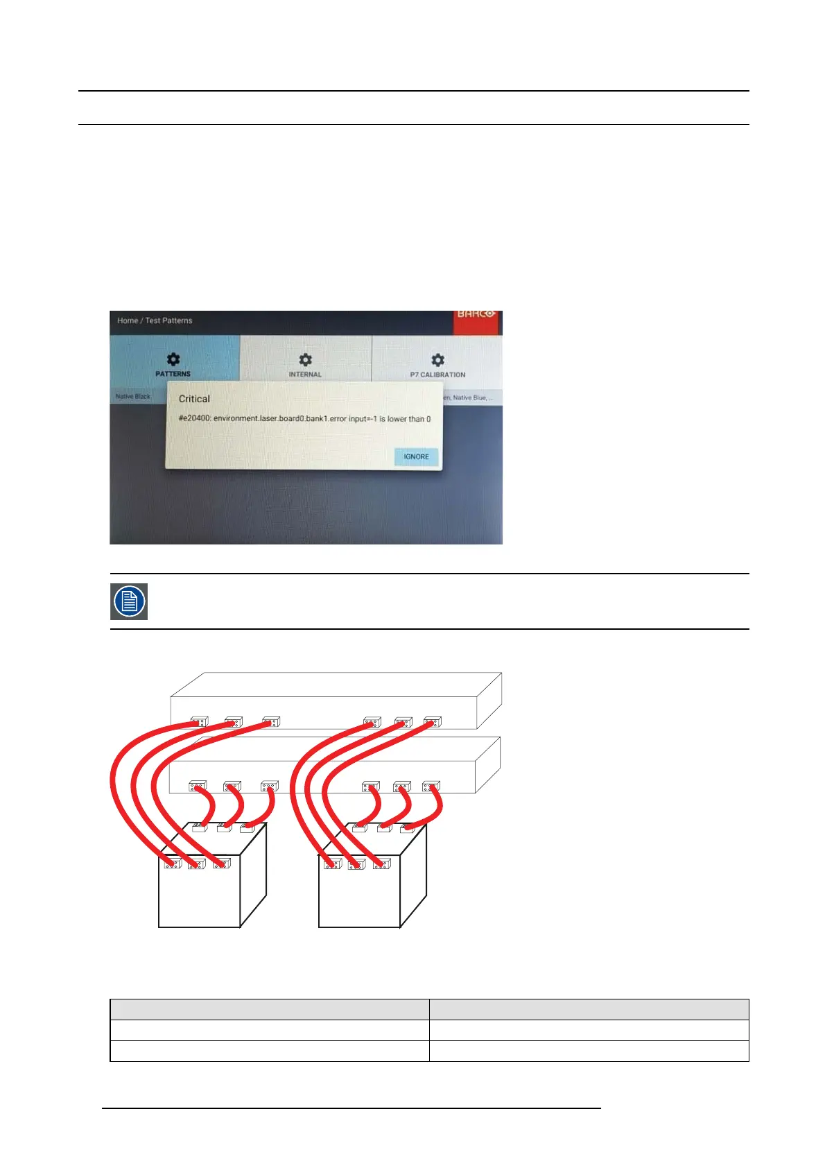
The error message may appear in OSD as illustrated below.
Image 5-6
See also the erro r code/failure m atrix, in the n ext pag e and the block d iagram for an overview of the system.
Block schematic diagram for the Laser driver system.
Cluster Left
Cluster right
Cluster right
0 1 2 3 4 5
0 1 2 3 4 5
0 1 2
0 1 2
3 4 5
3 4 5
Laser driver board
Lower (0)
Laser driver board
Upper (1)
Image 5-7
Error Codes regarding the Laser drivers
Error Message
Possible root c ause / Components to be replaced
#e20400 environmen t.laser.board1 .bank0.errorinput Laser cluster left
#e20400 environmen t.laser.board1 .bank1.errorinput Laser cluster left
24 723–0016 F90 01/12/2017