19. Disassembly / Assembly instructions
Similar on both sides of the rear cover
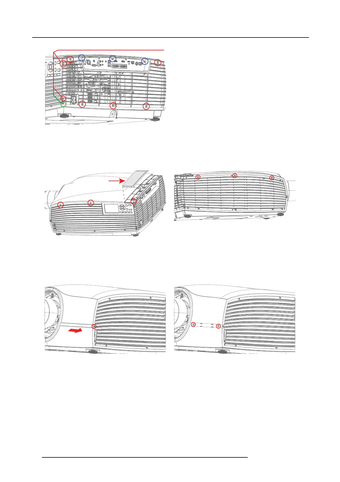
Image 19-3
19.2.3 Remove the main top cover
1. Remove 2 screws on the left s ide, 1 screw on the left rear top (Rear top cover must be removed), and 3 screws on the right side.
All screws are T 20 M4x10.
Rear top cover
Image 19-4
Image 19-5
2. Remo ve screw, T08 M2, 5x5, indicated by the red circle, se curing the front cover. Pull out the front cover in the direction indicated
with th e arrow.
Repeat this step for the front c over and screws on the other side of the lens opening as well. T he IR Re ceiver is also located
under the right body trim list.
3. W hen body trim is remov ed, two more T20 M 4x10 screws become visible. R em ove them.
Image 19-6 Image 19-7
4. Disconnect the LED Cable in the r ear end of the top co ver by sim ultaneously pressing down the tab on the top o f the connector,
indicated by the arrow, and pull
out.
82
723–0016 F90 01/12/2017