19. Disassembly / Assembly instructions
Image 19-11
19.3 Removing peripheral”mini” PCB’s
19.3.1 PCB GP6 IR Receiver and LED Board TOP
IR Receiver
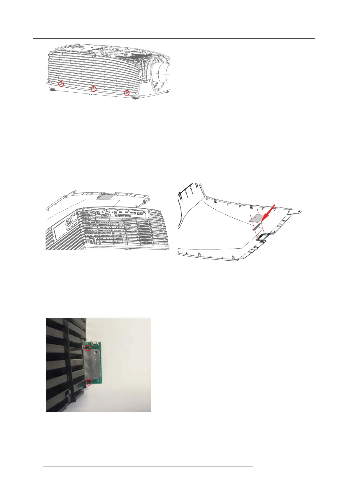
1. Remove 2 screws (TX8 PT 25x8) securing the PCB IR Receiver board to top cover. Lift up the PCB. The LE D lens can now also
be removed. W hen reassembling, be sure to position the tabs in an upwards position, as indicated by the red arrow.
Location of
IR receiver board
Image 19-12
Observe the tab
Image 19-13
IR receiver assembly
19.3.2 PCB Front USB & Trigger board
USB
1. Remove 2 screws (Tx10 M 3X6 ) and release the USB PCB from the me tal USB bracket.
Note: For information: The bracket is secured to the Cover Left with tw o screws (TX10 M3x8).
Image 19-14
19.3.3 PCB IR Front
1. Pull the IR Cov er incl. P CB IR up and out of the holder.
84
723–0016 F90 01/12/2017