24. Lens shift assembly
24.2 Lens position sensors (Horizontal and Vertical)
Item number: 534- 0031-xx 390 S ensor Optical End H
Release 2 screws (M3x8 TX10 W/Lockw.) to remove optical limit sensors.
- Left hand side limit sensor for horizontal sh ift connect s to PCB lens h ub connector J18
- Lower limit sensor for vertical shift con nects to J19
Image 24-4
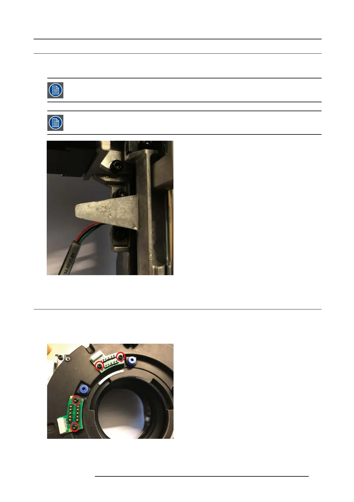
24.3 PCB lens connectors
1. Release 2 screws (M3x8 TX10) to remove each PCB lens conn.
- Left PCB is traditional PCB lens communication. Connec ts to PCB Lens Hub J7
Top PCB is responsible for logical c omm unication, storing of lens positions (Next EN6x series lens generation). C onnects to PCB
lens Hub J40
Image 24-5
723–0016 F90 01/12/2017 125