26. Technical Operations
1. Disconnect the PSU cables.
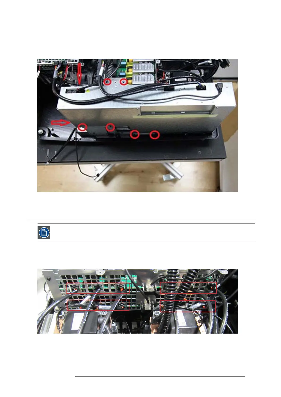
2. Remove the 8 screws (Tx10 M3x6) securing the PSU in place.
3. Lift the P SU out of the c hassis.
Image 26-9
26.5 PCB Laser Drivers
The two laser drivers are stacked in a ca ge. Each of the d rivers can be removed separately in the unlikely
event of malfunction. The complete assembly (laser driver pair) can be rem oved to gain access to other parts
of the projector.
26.5.1 Remove the Laser driver cage
1. Disconnect the 12 Molex connectors.
Image 26-10
2. Remove 4 screws TX10 (Tx10 M3x6) 2 pc s on the Blac k PCB Hub board bracket an d 2 securing F an Laser dr iver to the bottom.
3. Remove 6 pcs screws (Tx20 M4x8) s ecuring Laser d river cage to B ottom assy
723–0016 F90 01/12/2017
137