26. Technical Operations
Image 26-1
Image 26-2
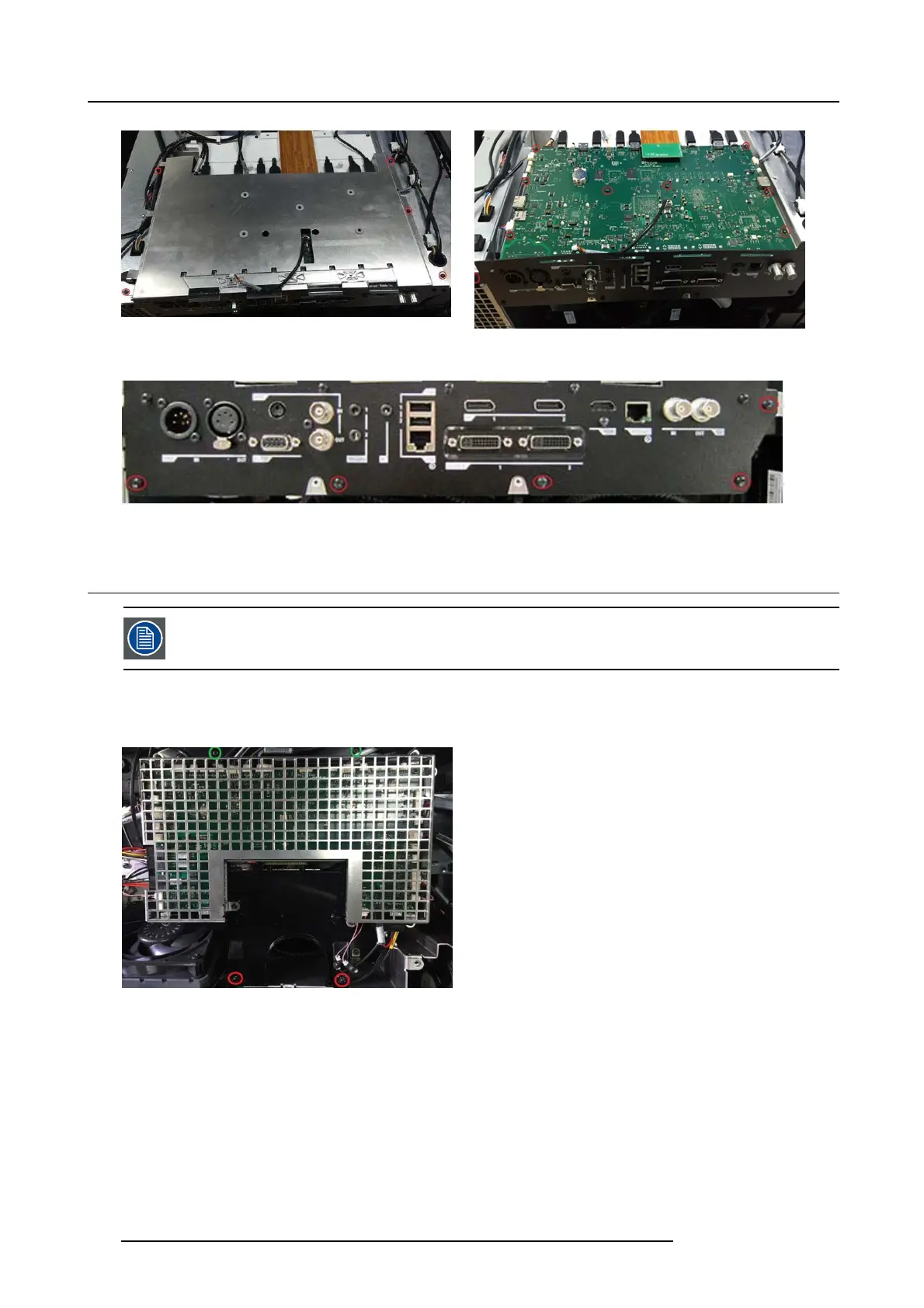
3. Remove 5 s crews (T10 M3x6) in rear cover and lift out PCB main.
Image 26-3
26.3 PCB Th ermal Hub board
To allow easier access during t he following procedures, the PCB lens hu b b oard including bracket Hub board
top and bottom can be removed.
1. Disconnect all cables, remov e 4 s crews (Tx10 M 3x6)
2. Release 2 screws (Tx10 M3x8) towards the lens.
Image 26-4
3. Release 7 screws (Tx10 M 3x6) and remove Bracket Hub Top.
4. Remove 8 screws (Tx10 M3x10), disconnect all c ables and remove the board.
134
723–0016 F90 01/12/2017