26. Technical Operations
26. T ECH NICAL OPERATIONS
26.1 PCB B racket bottom and Bracket fan
About
This section outlines replacement of parts without any pre-defined life cyc le.
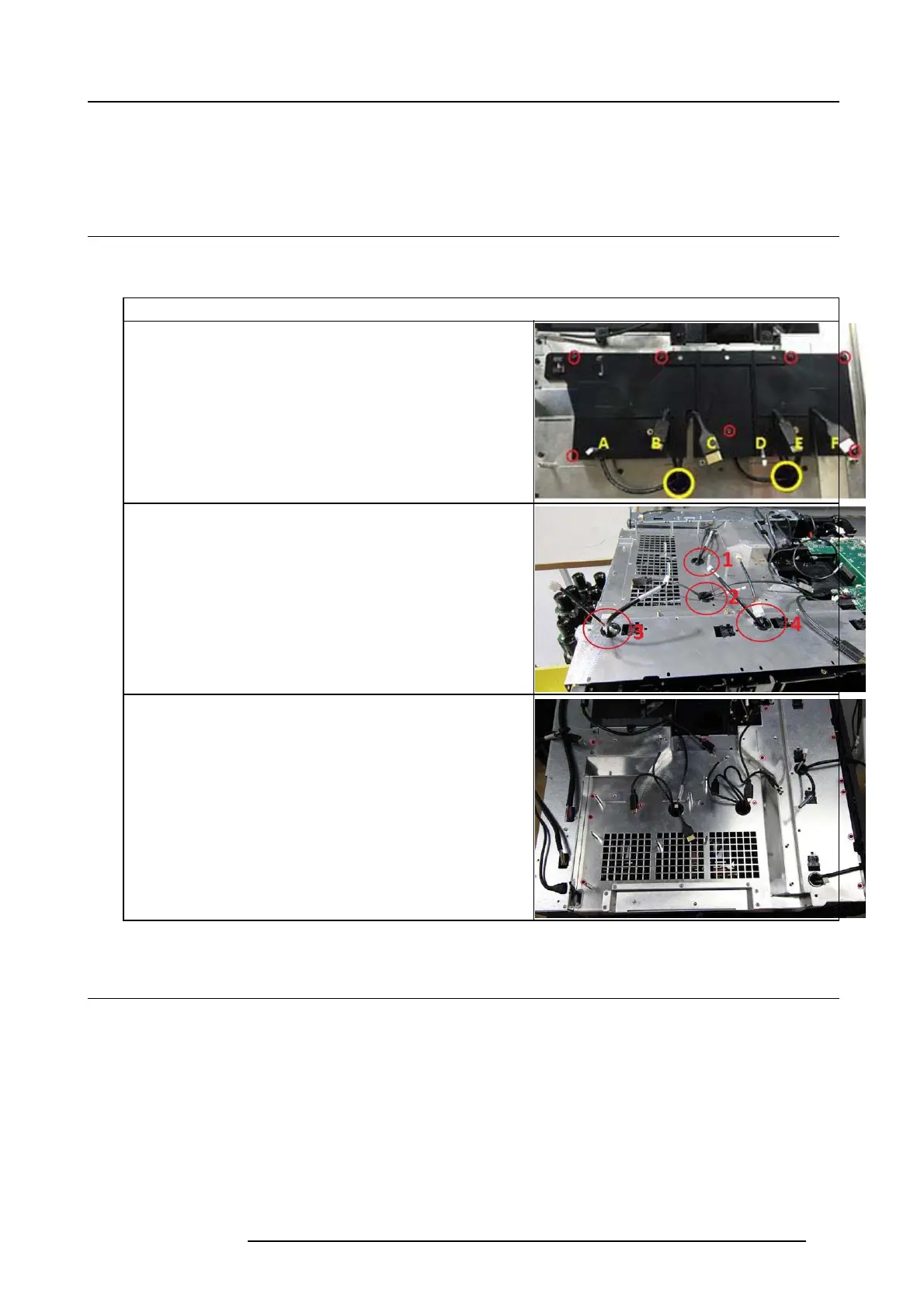
1. Remove the 7 screws (T10 M 3x6) releasing PCB B racket.
A. SwThermal PD Left Loop (Small cab le)
B. Ctrl LD left (Larger)
C. CW (Largest)
D. SwThermal PD Right (Small)
E. Ctrl LD right (Larger)
F. PW _R (Largest)
Cable Routing
1. Switch Thermal (Bimetallic witch loop1), Laser Driver 1 Output &
Comm. Phosphr whee l 1.
2. Switch Thermal (Bimetallic witch loop2), Laser Driver 2 Output &
Comm. Phosphr whee l 2.
3. Cables from Fans in F rame rad iator rear, Cables form F rame Radiator
4. Cables from two radiator fans.
5. Remove 14 screws (T10 M3x6) and lift out PCB B racket bo ttom.
26.2 PCB Main
1. Remove 10 screws (Tx10 M3x6) to release bracket PC B Top
2. Disconnect all cables, remove 8 sc rews (Tx10 M3x6) on top of PCB main.
723–0016 F90 01/12/2017
133