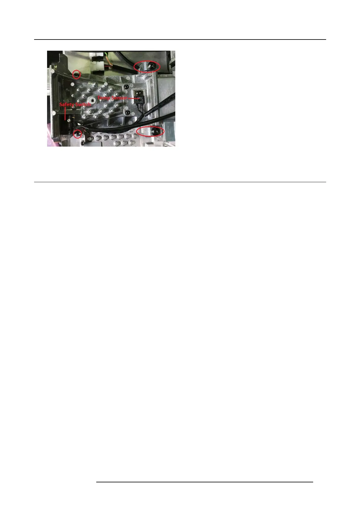
21. DMD, DMD Board, CLGA & DMD heatsink elements
Image 21-16
21.9 Install new Laser Interface
1. Position the new Laser Interface to the TI loop.
2. The interface will “fall in” to a track , and will not be pos sible to rotate vertically when it is in correct pos ition. T he line between the
interface and the TI Loop will be narrow and paralell.
3. Hold the interface in place with one hand, while entering the two M4x 12 screws, and thereafter apply the clam ps and tighten
them up. E nsure correct position and fit also for the clamps.
4. Fasten the two screws securing the new laser interface to the b ase plate (Tx20 M4x12)with 1,5nm Torque.
Caution: There shall be no bias between the laser interface and the TI Loop. Th is is a safety issue. This will be obtained using
the method described abov e.
723–0016 F90 01/12/2017 109