21. DMD, DMD Board, CLGA & DMD heatsink elements
Image 21-2
3. With complete assy removed, clean the heatsink surface with B rake & Clutch cleaner. A pla
stic card may be used first to remove
old heat paste first.
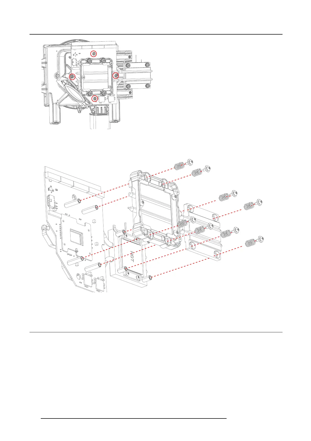
4. Split the complete heatsink assembly by removing 4 +4 screws (TX 10 M3x8) using an X-sequence.
Image 21-3
Note: Heatsink stud and cooling surface may be b onded to DM D and Front side heatsink by the thermal paste. Some force
may be required to sp lit the two hea tsink assemblies.
21.3 GP6 PCB DM D Board
1. Remove 4 screws (Tx8 M25x10) diagonally
2. Carefully remove the DMD backer p late.
3. Remove 4 spacers (4mm he x) and release the D MD board.
104
723–0016 F90 01/12/2017