26. Technical Operations
Image 26-11
Image 26-12
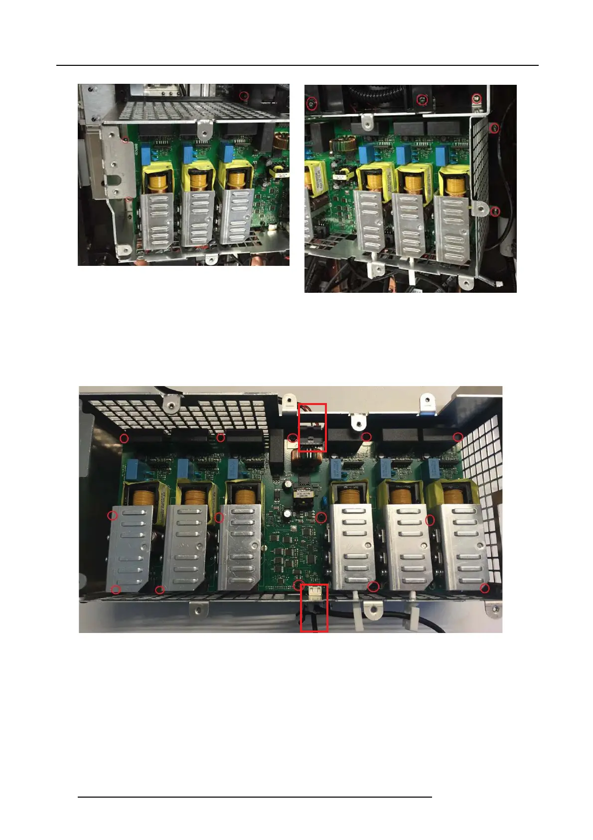
26.5.2 Remove the Laser driver PCB board
1. 1. Release the 2 quick con nect clips and disconnect the two HDMI cables.
2. 2. Disconnect the Power inlet co nnectors.
3. 3. Rem ove 14 screws (Tx10 M3x6) and carefully lift out the PCB Laser dr iver.
Image 26-13
26.5.3 Remove the Bottom laser driver PCB board
1. Remove 14 spacers (50mm M3x45)
2. Disconnect Power inlet socket be fore removing the P CB.
3. Lift out the PCB Laser Driver.
138
723–0016 F90 01/12/2017