21. DMD, DMD Board, CLGA & DMD heatsink elements
21. D MD, DMD BOARD, CLGA & DMD HEATSINK
ELEMENTS
The complete Assembly must first be separated com pletely f rom core engine before split down further, ac-
cessing DM D, DM D board, and CLGA and DMD heatsink elements.
Always unscrew and tighten the screws in diago nal order.
All dove clamp screws shall be tighten wit a torque of 3,1Nm.
21.1 DMD assembly
Location
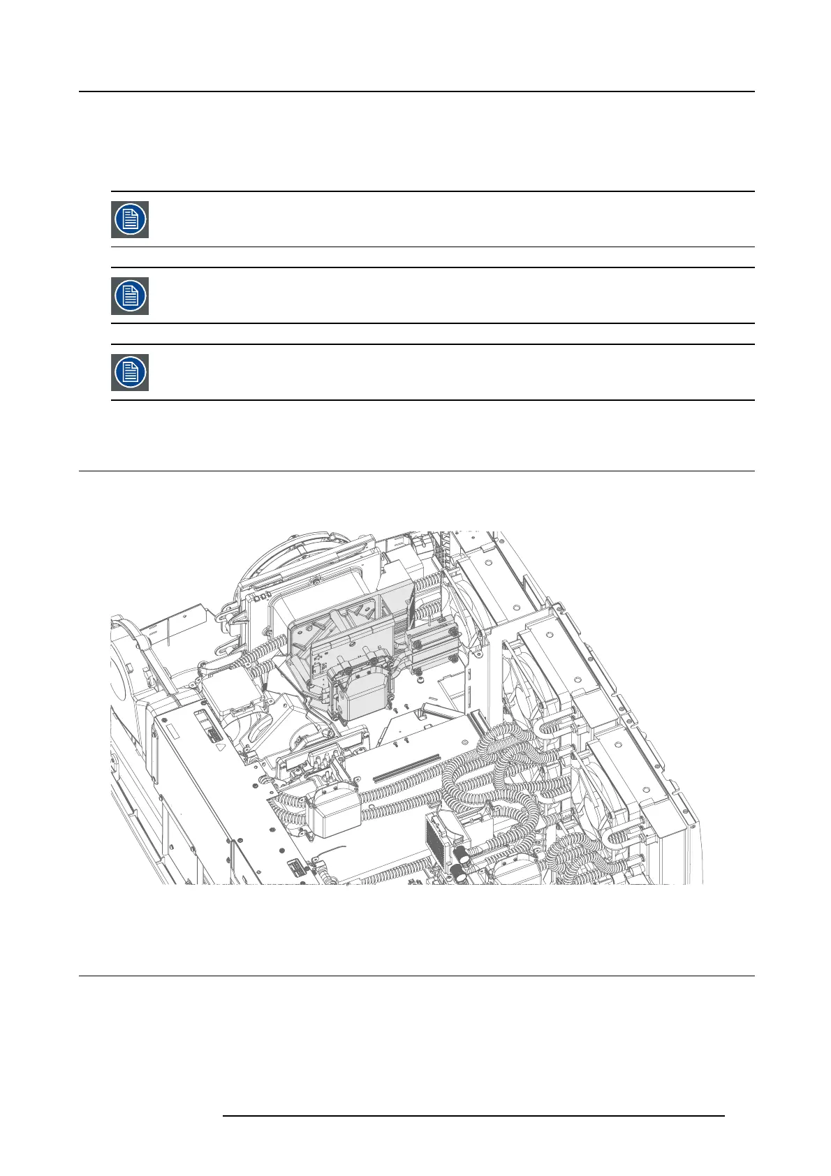
The DMD assembly is highlighted in the illustration below.
Image 21-1
Location of the DM D module.
21.2 DMD Board, CLGA & DMD heatsink elements
1. Remov e the liquid cooling p
ump as described above in section "Laser Clus ters B lue (2pcs)", page 91.
2. Remove 4 spacers (4mm hex) in a diagonal order, re move the complete DMD assembly.
723–0016 F90 01/12/2017
103