22. TI Loop
22.2.9.2 Converging Lens (Exit)
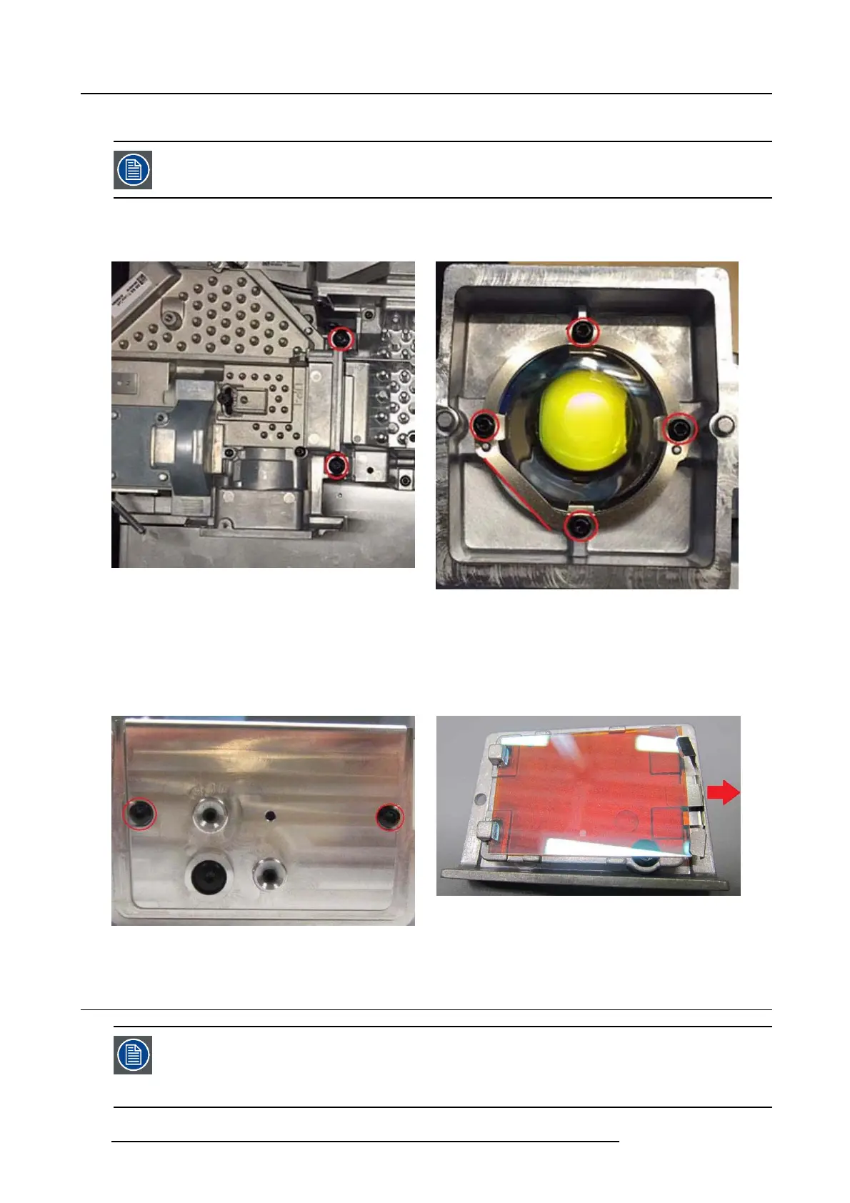
In order to access the exit len s, the TI loop must be separated from the illumination engine.
Ensure the TI loop cover is m ounted before you release the TI Loop.
1. Release two screws (TX20 m50 X45) holding the Dow Tail clam ps. This releases the TI loop form the Illumination Engine Front.
2. Release 4 s crews (Tx8 M2.5x6) holding the clip and lens.
Image 22-16
Image 22-17
22.2.10 Adjusting Mirror
1. 2. Remove 2 screws (TX8 M2, 6x6).
2. 2. Pull clips in the direction of the red a rrow using a sharp implement (e.g. tip of scalpel) and replace M irror blue.
Image 22-18
Image 22-19
22.3 TI Loop Right
You may need to use a screw d river or sim ilar to g ently bend loose the l ight path from the rem aining optical
engine.
Most components inside TI Loop right are mounted following same procedure as documented for left loop.
Exceptions are docu mented in the following chapter.
116 723–0016 F90 01/12/2017