19. Disassembly / Assembly instructions
Image 19-17
19.4 Display and keypad Module.
The display and keypad module is a complete assembly. Part Number - R 8768011K 4K Display Module.
1. Refer to chapter 19.2.1.4 “Remove the left s ide cover”, and perform this procedure.
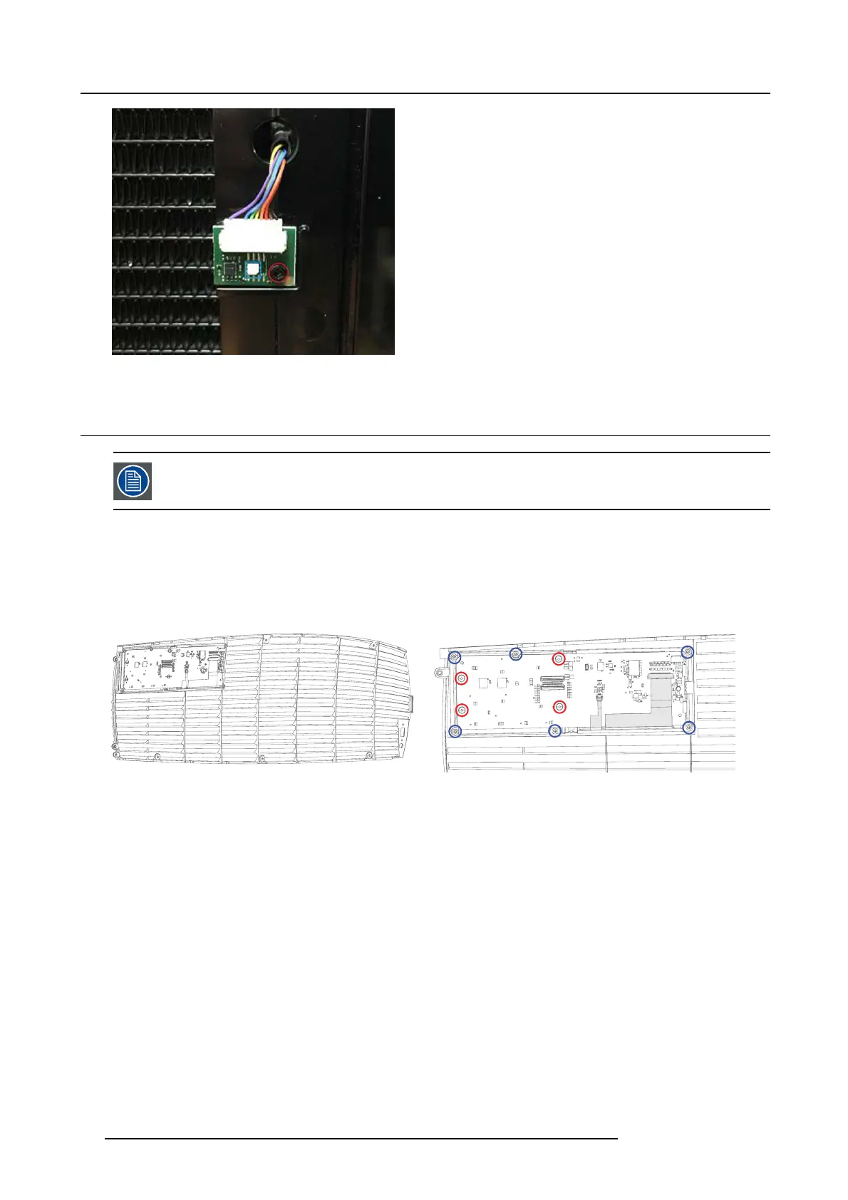
2. Remove 6 screws indicated by the blue circles, to re move the complete display and keypad module from the side cover.
3. For splitting the keypad from the PCB, remove the screws indic
ated by the red circles.
4. Reassemble the mo dule in reverse order.
Image 19-18
Location of the display/keypad module
Image 19-19
86 723–0016 F90 01/12/2017