23. Illumination Engine front
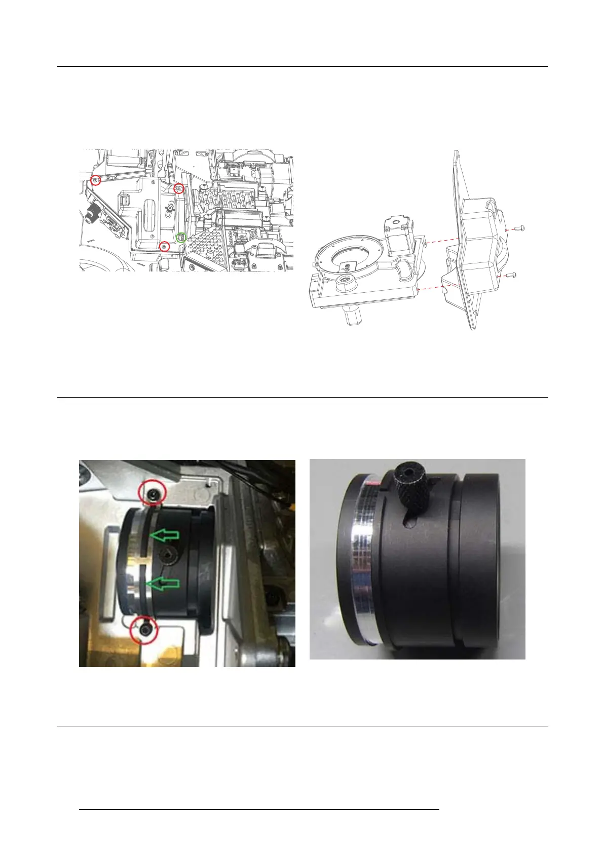
Remove Iris assembly
1. Remove 3 screws (TX 8 M2.5x6) and carefully lift out Illumination Iris cover including IRIS assy.
2. Take note of cable r outing of limit switch through groove in Illumination Iris cover, as illustrated (green) in picture below.
3. Release I ris assy from the cover
Image 23-3
Removing Iris assembly incl cove r.
Image 23-4
Releasing iris ass embly from the cover.
23.2 Relay Tube assy
1. Remove two screws (TX8 M2 .5x6), the clips and carefully lift out as sem bly.
2. In order to p lace the lens in correct position when assembling the Relay tube, use trace in the clip to match gr ove in lens. Note!
See Optical adjustment chapter 10.2 for adjustment of relay tube lens after service.
Image 23-5
Image 23-6
23.3 PCB CLO (Constant Light Output) .
1. Remove Fan Optics.
2. Remove 4 screws (Tx10 M 3x6) securing the PCB to the CLO holder (TX10 I min, 8 I EW I)
120
723–0016 F90 01/12/2017