19. Disassembly / Assembly instructions
2. Slide the P CB IR out from c over and disconnect the cable from the P CB thermal Hub.
Note: The IR cover, including PCB IR, is he ld in place by the top cover once t his is mounted.
Image 19-15
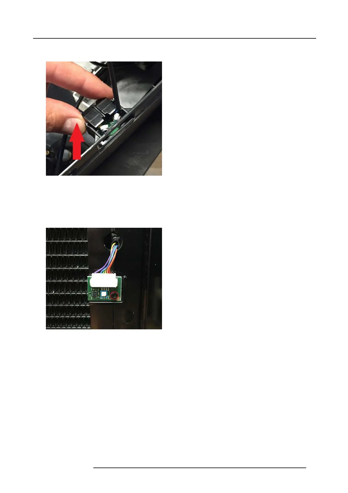
19.3.4 PCB Inlet temp sensor board No1.
1. This PCB is located on the frame radiator back.
2. Disconnect the cable and remove one screw (T8 M 2,5x6)
Note: Do no t touch components on the board directly during handling; always hold the boa rd edges!
Image 19-16
19.3.5 PCB Inlet temp sensor board No2.
1. This PCB is similar to the P CB inlet board, ref. 18.3.4, and located the bac k side of the radiator fans.
2. Disconnect the cable and remove one screw (T8 M 2,5x6)
Note: Do no t touch components on the board directly during handling; always hold the boa rd edges!
723–0016 F90 01/12/2017 85