19. Disassembly / Assembly instructions
Image 19-8
5. Then the top cover can be removed by gently pry the cover upwards.
19.2.4 Remove the Side cover left
1. Remove 2 pcs Tx10 M3x8 screws on the front end o f the left side panel, in order to r elease the Front US B and Trigger boa rd
from the side panel. Indicated by the blue circles.
Image 19-9
2. Remove the 3 screws T x 20 M4x 10 indicated by the red circles, and ge ntly move the panel a bit out, and disconnect the two cable
from the PCB
Note: Caution must be exercised when the cover is removed due to the two cables that still are c onnected to the pcb on the
inside of the side cover.
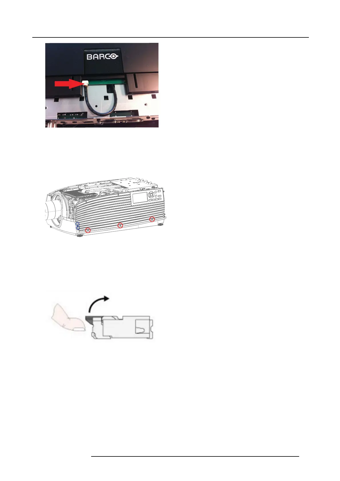
3. Disconnect the F lex Cable from the Back Panel PCB by gently lifting up the tab on the connector and remo ve cable from the
connector. This is sensible components – do not use high forces for this proc edure.
Note: Be careful with flex cable and locks. The y are fragile components.
Image 19-10
Principle of flex cable locking mechanism. Flip lock connector.
4. 5. Disconnect the s econd cable.
5. 6. Carefully remove the s ide panel from the unit.
19.2.5 Remove the Side cover right
1. 1. Remove M4x10 screws on the right s ide indicated with red circles. Use a TX20 screw driver. Carefully lift out the right c over.
723–0016 F90 01/12/2017
83