22. TI Loop
22.2 Overview Engine assembly
Lens shift motor vertical
Lens shift motor horizontal Peltier front Peltier rear
NTC Front
NTC rear
IR LED
Fan IR Thermal Switch right
Thermal Switch left
Laser Cluster Left
Laser Cluster right
Fan IR
Iris motorFilter motor
CLOLens banana board
End switch
PW left
PW right
Color wheel
IR LED
Laser Cluster connectors
Laser Cluster connectors
End switch
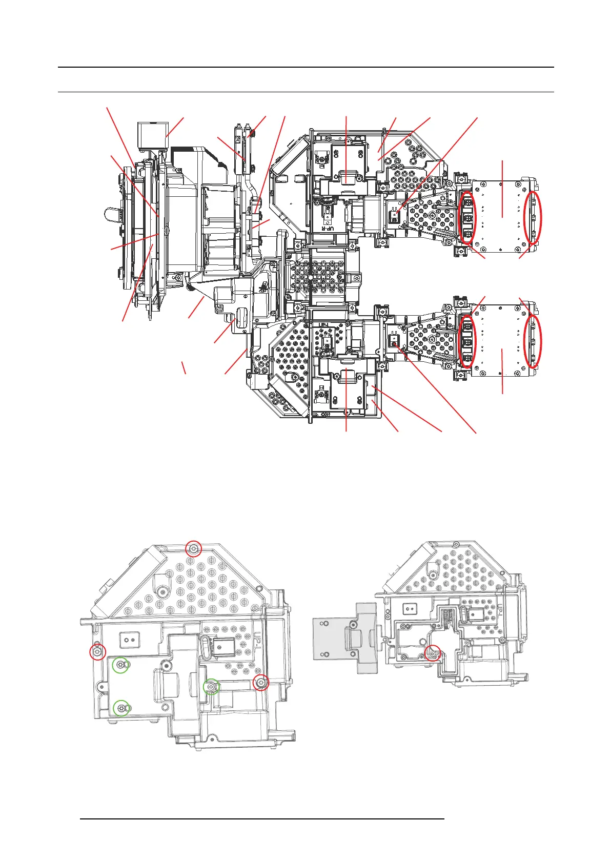
Image 22-2
22.2.1 TI Loop Left
1. Remove 3 outer s crews (Tx10 M3 X6).Mar
ked with r e d circles.
2. Remove 3 screws (TX8 M2.5x6) marked with green circles, and then the PW Cover.
Once the cover is removed, the 5th TX10 M3X 6 screw will be v isible and yo u will b e able to remove Engine Blue Loop Top.
Image 22-3
Image 22-4
112 723–0016 F90 01/12/2017