10. Optical adjustments
1
2
Image 10-6
Focus adjustment location
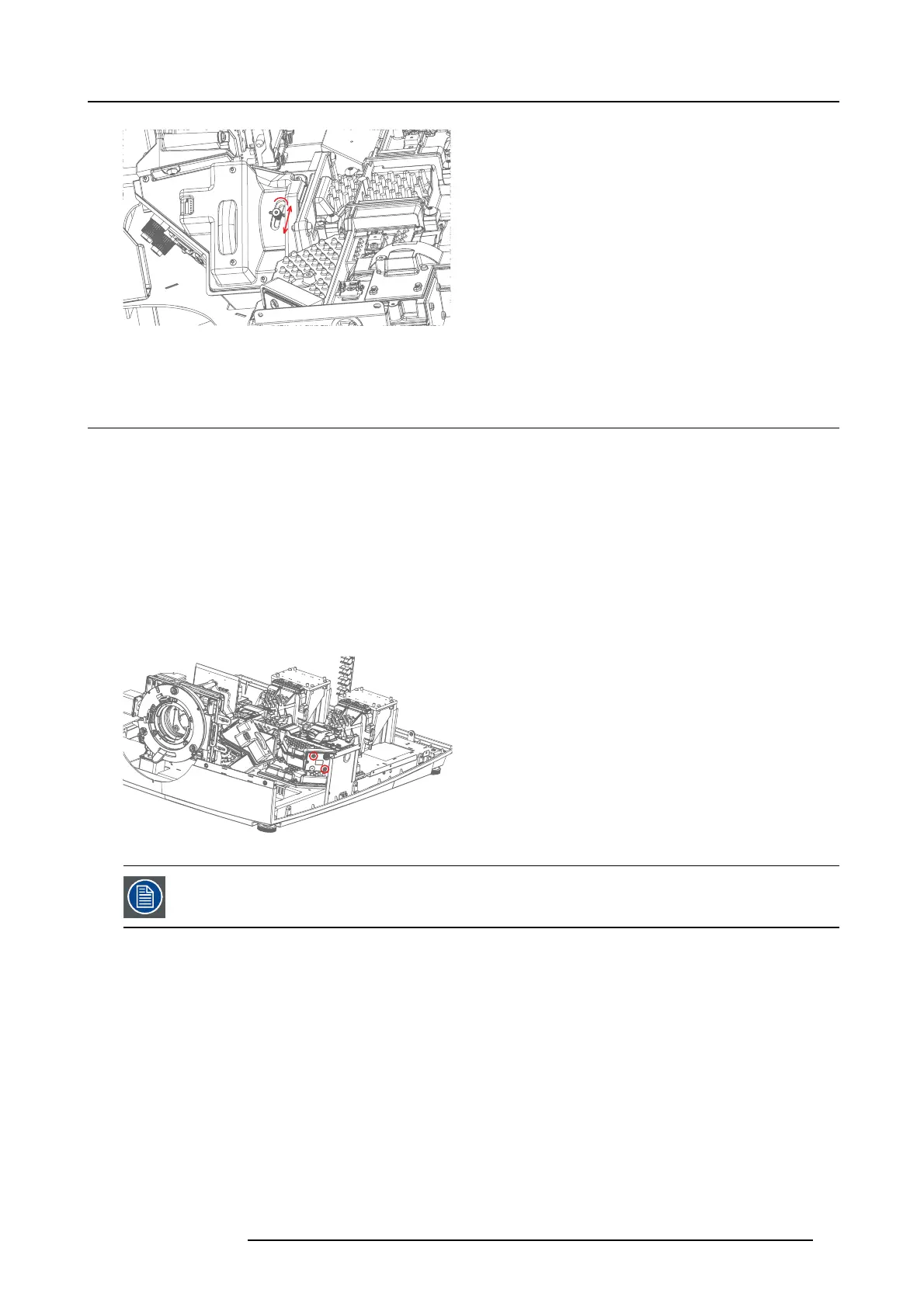
10.6 Color Uniformity, TI Loop mirrors adjustment
• Use full white test image
• Tool: 1,5mm hex
Purpose of adjustment is to even the center the brightness. Adjust one leg at the time. Turn off right laser cluster wh ile adjusting left
mirror and v ice versa. This can be done by use of Prospector web interface (see chapter 11, P W adjustment).
10.6.1 Color Uniformity, left TI Loop mirror:
The uniformity ad justment is quite delicate adjustment to perform. Should not be attempted unless absolutely needed.
The upper left screw (1) adjusts the Hor izontal (X) uniformity while the right screw (2 ) is for Vertical uniformity (Y ).
Adjust by eye until you are satisfied or measure white point in edges of im age and compare.
Note! In order to adjust one leg accurately, the alterative light source must be shut off. See chapter 13.3 for details
1
2
Image 10-7
If a yellow spot can’t be adjusted aw ay. If image is t o yellow either o n left o r right leg: Adjust mirror on C olor
Uniformity, left TI Loop mirror:the opposite led/TI loop so that you get a blue spot on the same location. This
will can cel out the yellow when both clusters are lit.
10.6.2 Color Uniformity, Right TI Loop mirror:
Adjust using same method.
Adjustment screws for right T I loop are acc essible from outside of the unit, after rem oval of the right side cover.
Before starting the adjustment, outer side cov er right and frame radiator right protection grid m ust be removed (see chapter 17.3.5).
The lower right s crew (1) adjusts the Horizontal (X) uniformity while the upper left screw (2) is for Vertical uniformity (Y).
723–0016 F90 01/12/2017
45