Confidential
3-53
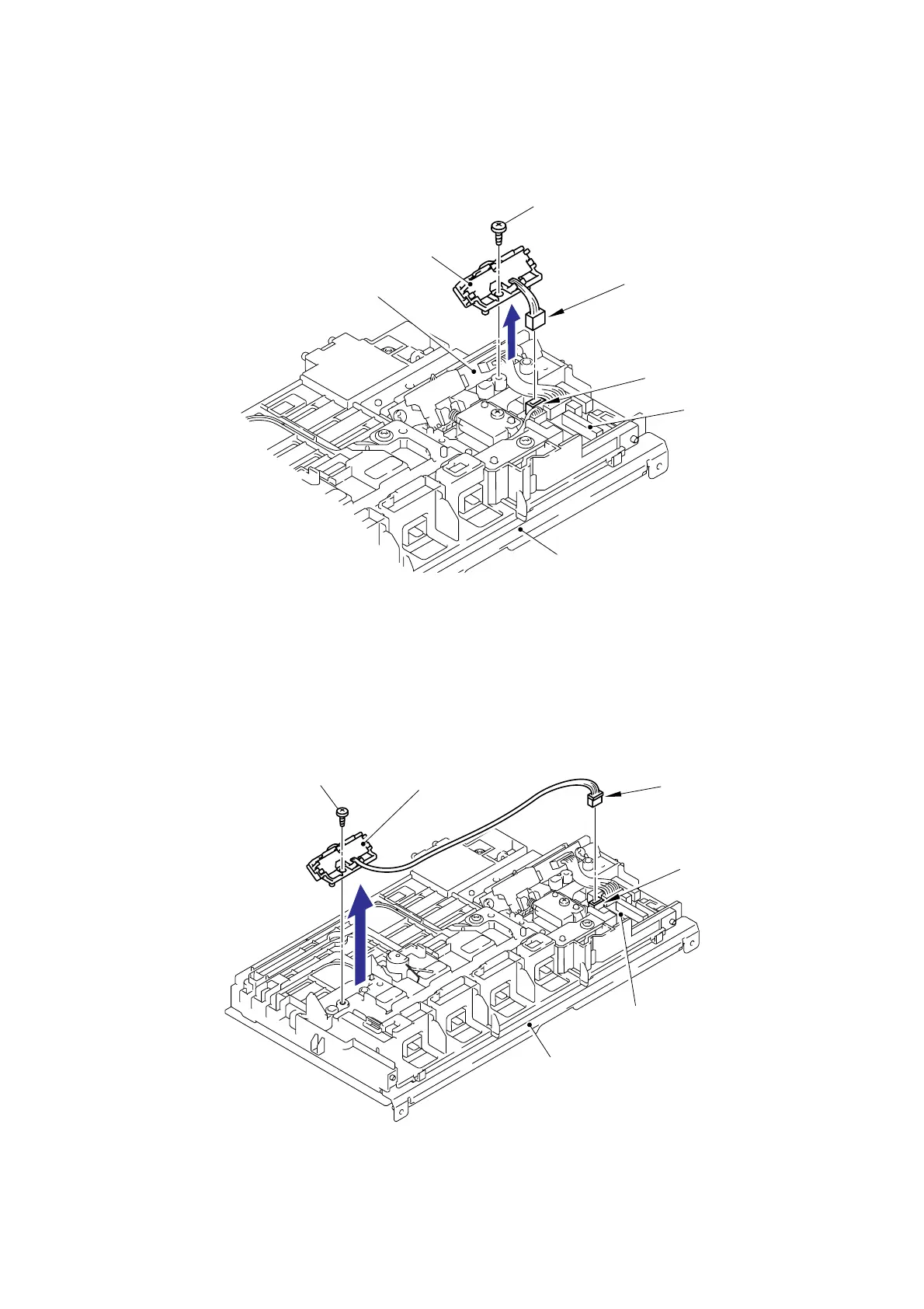
(4) Disconnect the Connector (CN3) of the Registration-mark sensor PCB ASSY 1.
(5) Remove the bind B M3x8 Taptite screw, and then remove the Registration-mark sensor
PCB ASSY 1 from the Density sensor holder.
Fig. 3-36
(6) Disconnect the Connector (CN4) of the Registration-mark sensor PCB ASSY 2.
(7) Remove the bind B M3x8 Taptite screw, and then remove the Registration-mark sensor
PCB ASSY 2.
Fig. 3-37
Taptite, bind B M3x8
Transfer HVPS PCB unit
CN3 (Blue)
Registration relay PCB ASSY
Registration-mark sensor PCB ASSY 1
Transfer HVPS PCB unit
CN4 (White)
Registration relay PCB ASSY
Taptite, bind B M3x8
Registration-mark sensor
PCB ASSY 2
Connector
Connector
Density sensor holder

 Loading...