Confidential
3-64
8.18 Pull arm L, R/ Hinge Protection Cover ASSY
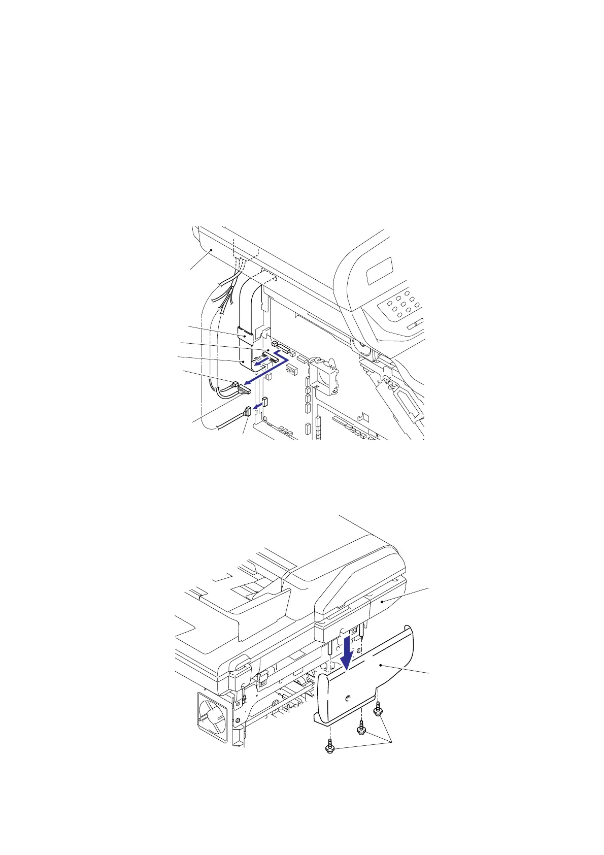
(1) Disconnect the three Connectors (CN14, CN16, CN21) from the Main PCB ASSY.
(2) Disconnect the Flat cable (CN17) from the Main PCB ASSY, and then pull out the Flat
cable from the Core.
Note:
- After disconnecting the flat cable(s), check that each cable is not damaged at its end or
short-circuited.
- When connecting the flat cable(s), do not insert it at an angle. After insertion, check that
the cable is not at an angle.
Fig. 3-53
(3) Remove the three cup B M4x12 Taptite screws, and then remove the Hinge protection
cover ASSY.
Fig. 3-54
Document scanner unit ASSY
Main PCB ASSY
CN21
CN14
CN16
Flat cable (CN17)
<Left side>
<Back side>
Document scanner unit ASSY
Hinge protection cover ASSY
Taptite, cup B M4x12
Core

 Loading...