Confidential
3-152
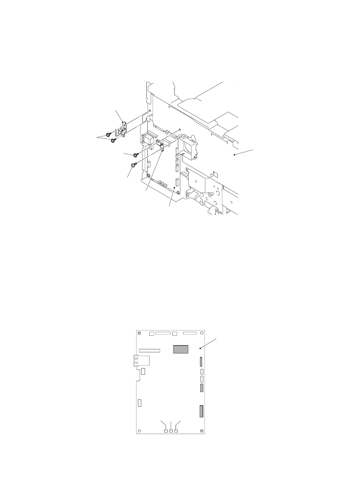
8.38 Main PCB ASSY/ Ground Plate/ Ground Spring Plate
(1) Remove the cup S M3x6 Taptite screw and bind B M4x12 Taptite screw, and then remove
the Ground plate.
(2) Remove the two cup S M3x6 Taptite screws, and then remove the Ground spring plate.
Fig. 3-214
*1
Tightening Note:
When tightening the screw, slowly turn it counterclockwise (in the direction to loosen the
screw) with your hand until you feel that the screw is a little dropped in the hole. Then,
slightly turn it clockwise (in the direction to tighten the screw) with your hand and tighten it
according to the specified torque with a screwdriver.
(3) Disconnect all the connectors from the Main PCB ASSY.
Note:
- After disconnecting the flat cable(s), check that each cable is not damaged at its end or
short-circuited.
- When connecting the flat cable(s), do not insert it at an angle. After insertion, check that
the cable is not at an angle.
CN1
CN3
CN2
CN16 CN10CN14
CN7
CN8
CN4
CN5
CN21
CN19
CN17
CN12
CN13
CN15
Fig. 3-215
Main PCB ASSY
Ground plate
Taptite, bind B M4x12
(Tightening torque: 1.20 ±0.1 N m) *1
Taptite, cup S M3x6
Taptite, cup S M3x6
Ground spring plate
Main PCB ASSY
Frame unit
<Left side>

 Loading...