8
Commissioning
62/130 ekr CON 100 – Installation and Operating Manual
NOTICE
Damage caused by operating the actuator in generator mode!
Operating the actuator in generator mode can lead to the destruc-
tion of the controller or the actuator.
►
Provide suitable measures for removing or converting the
resulting energy (e.g. external ballast circuit or electrically
isolating the actuator from the controller).
The controller is not fitted with a ballast circuit (brake chopper). If
the guiding device is moved by external mechanical forces (e.g.
when inserting rolls using a forklift in winding applications), the
actuator acts as a generator. In this case, suitable measures must
be provided for removing or converting the resulting energy.
8.2 Requirements
■ The web guiding system has been fully wired up, i.e. the cable
connections between the separate web guiding components
(controller, sensors, actuator, ...) have been made.
■ The controller is connected to the power supply.
■ All transport locking devices on the guiding device and actuator
have been removed.
8.3 Setting the DIL Switches
Before commissioning the web guiding system, you must set the
DIL switches of the controller according to the application.
NOTICE
Damage to the components from working on live parts.
►
Before opening the controller, switch off the power supply.
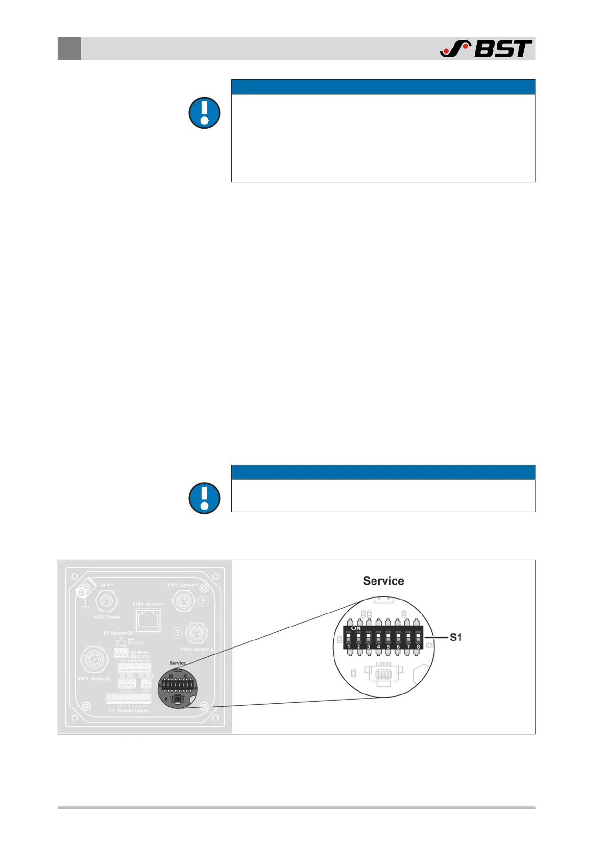
The DIL switch S1 is located behind the plastic plug (Service) on
the back of the controller.
Fig.26: DIL switch S1

 Loading...


