7
Electrical Connection
46/130 ekr CON 100 – Installation and Operating Manual
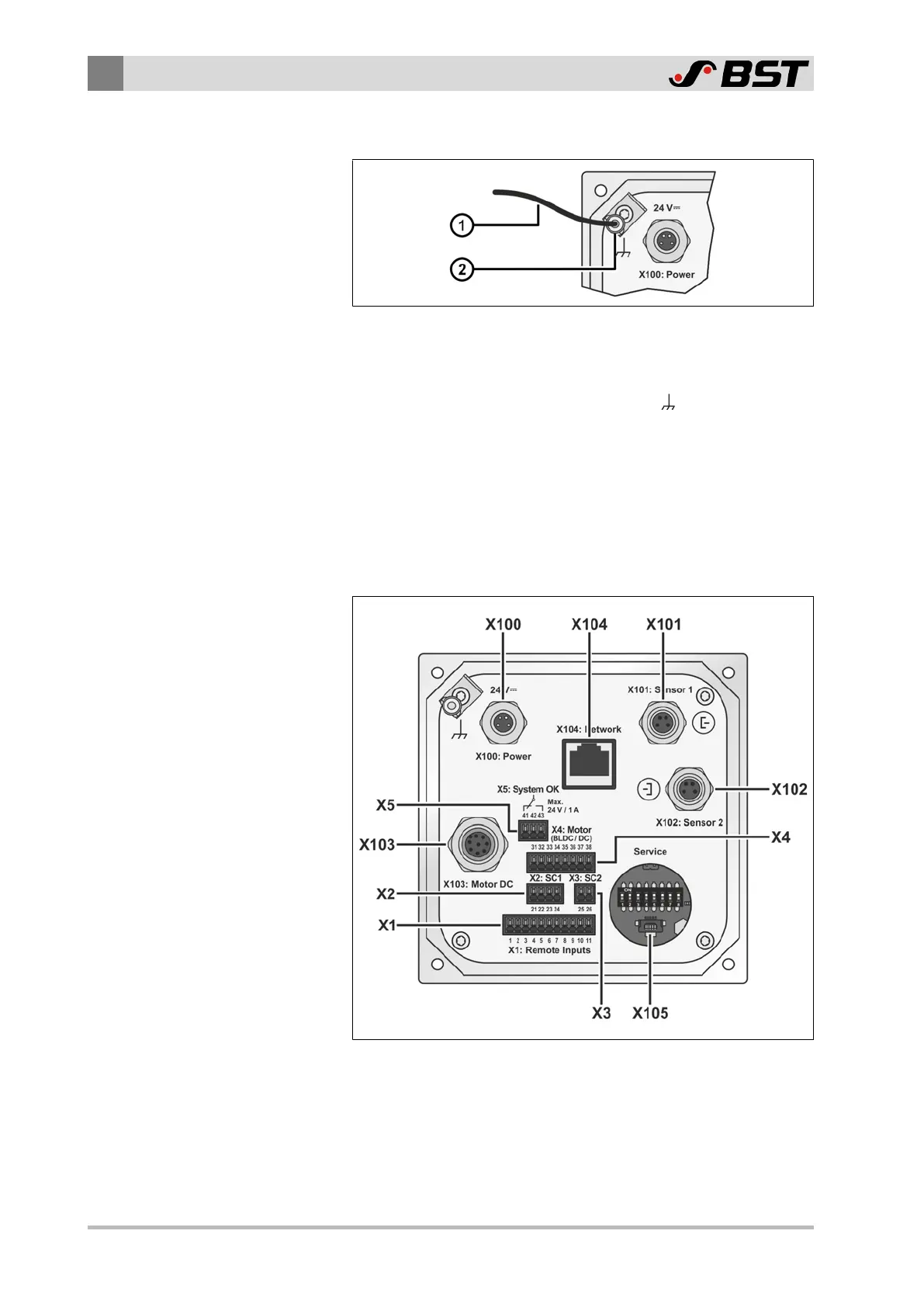
Installing the equipotential bonding at the controller
Fig.13: Flat-blade connection for the equipotential bonding
For the connection of a cable ① for the equipotential bonding
(wire cross section 1.5 – 2.5 mm
2
), please use the flat blade
receptacle ② at the flat-blade connection (
) on the back of the
controller.
7.5 Connections on the Controller
The sockets, plugs and terminal strips on the back of the controller
permit the connection of the different web guiding system
components as well as the networking with an external control
system.
Fig.14: Connections on the back of the device
You can find the function of the connections in the table on the
following page.

 Loading...


