Electrical Connection
7
ekr CON 100 – Installation and Operating Manual 57/130
7.7.5 X4 - Brushless motor / DC
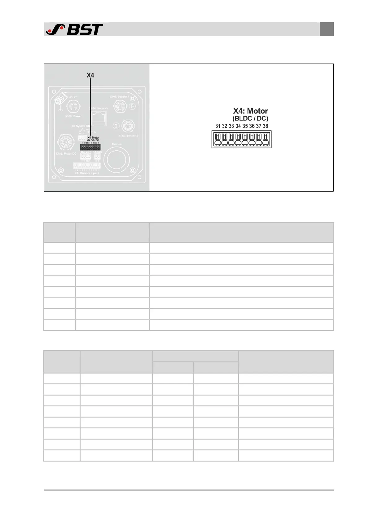
Fig.23: Terminal strip X4
Connection brushless DC motor (BLDC)
X4
Terminal
Function Note
31 Brushless motor, phase 1 Motor terminal
32 Brushless motor, phase 2 Motor terminal
33 Brushless motor, phase 3 Motor terminal
34 GND Ground
35 Hall 1 Rotor position sensor
36 Hall 2 Rotor position sensor
37 Hall 3 Rotor position sensor
38 +12V⎓ Output +12V⎓ (max. 0.1A)
Connection DC motor (EMS10, ECOEMS22)
X4
Terminal
Function Wire color Note
EMS10 ECOEMS22
31 Actuator A (+) brown red Output A to actuator
32
33 Actuator B (-) white black Output B to actuator
34
35
36
37
38

 Loading...


