Electrical Connection
7
ekr CON 100 – Installation and Operating Manual 59/130
7.8 Service Indications
7.8.1 Service LEDs Overview
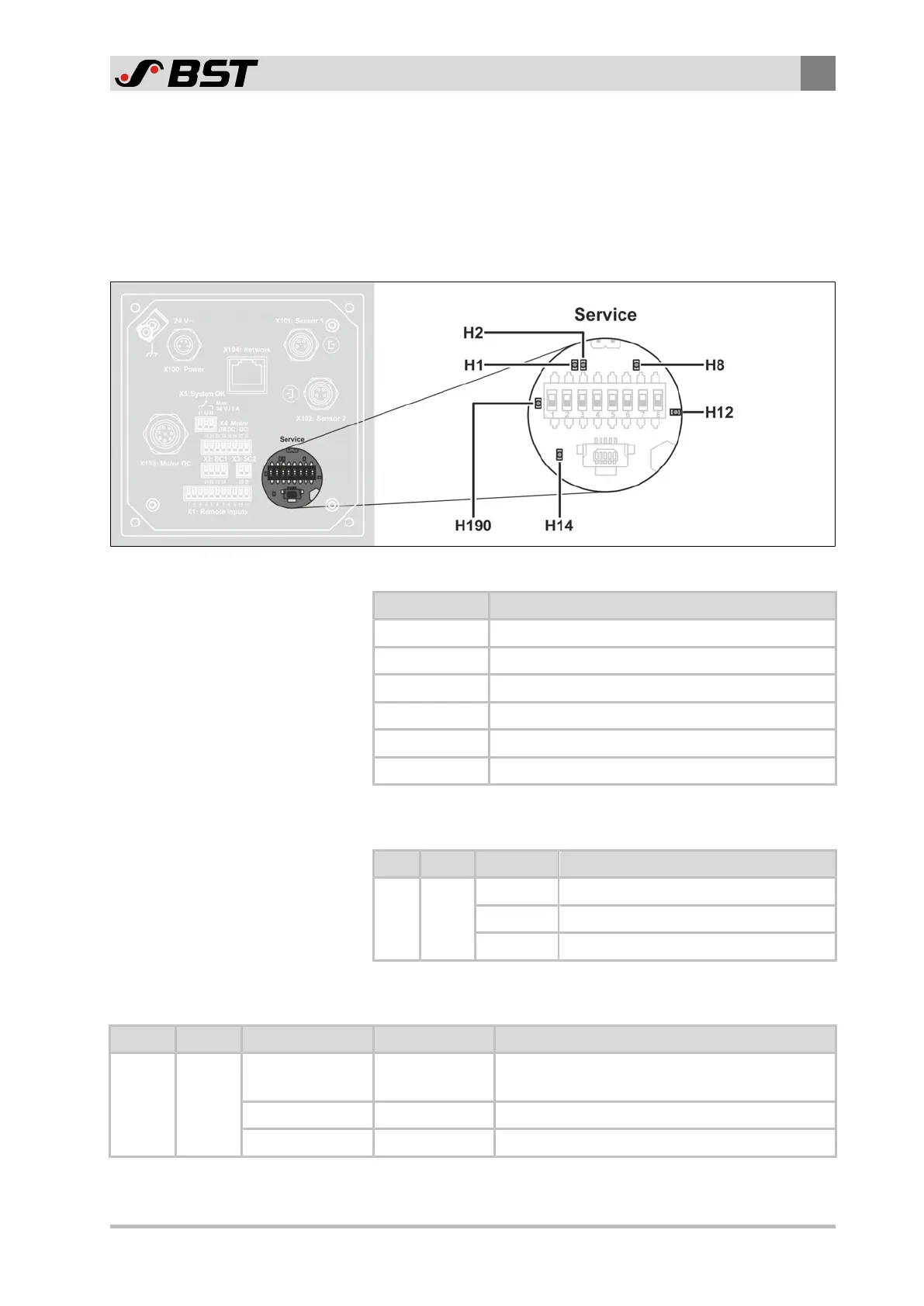
The following figure shows the position of the service LEDs on the
processor board of the controller. The service LEDs are located
behind the plastic plug (Service).
Fig.25: Service LEDs on the processor board
Service LED Display function
H1 reserved
H2 Device status
H8 Bus status
H12 Status of the power supply
H14 reserved
H190 Status of the message output “System OK”
7.8.2 Display of Device Status
LED Colour Condition Meaning
H2 green
OFF The unit is in an undefined state.
FLASHING The unit program is running correctly.
ON The unit is in an undefined state.
7.8.3 Display of Bus Status
LED Colour Condition Bus designation Meaning
H8 red
OFF NO ERROR
The module is working correctly.
No problems exist.
FLASHES x3 SYNC ERROR
No SYNC message is received.
ON BUS OFF The interface controller is located in Bus-Off mode.

 Loading...


