EasyManuals Logo

BST ekr CON 100 User Manual

BST ekr CON 100
130 pages
To Next Page IconTo Next Page
To Previous Page IconTo Previous Page
Page #49 background imageLoading...
Page #49 background image
Electrical Connection
7
ekr CON 100 – Installation and Operating Manual 49/130
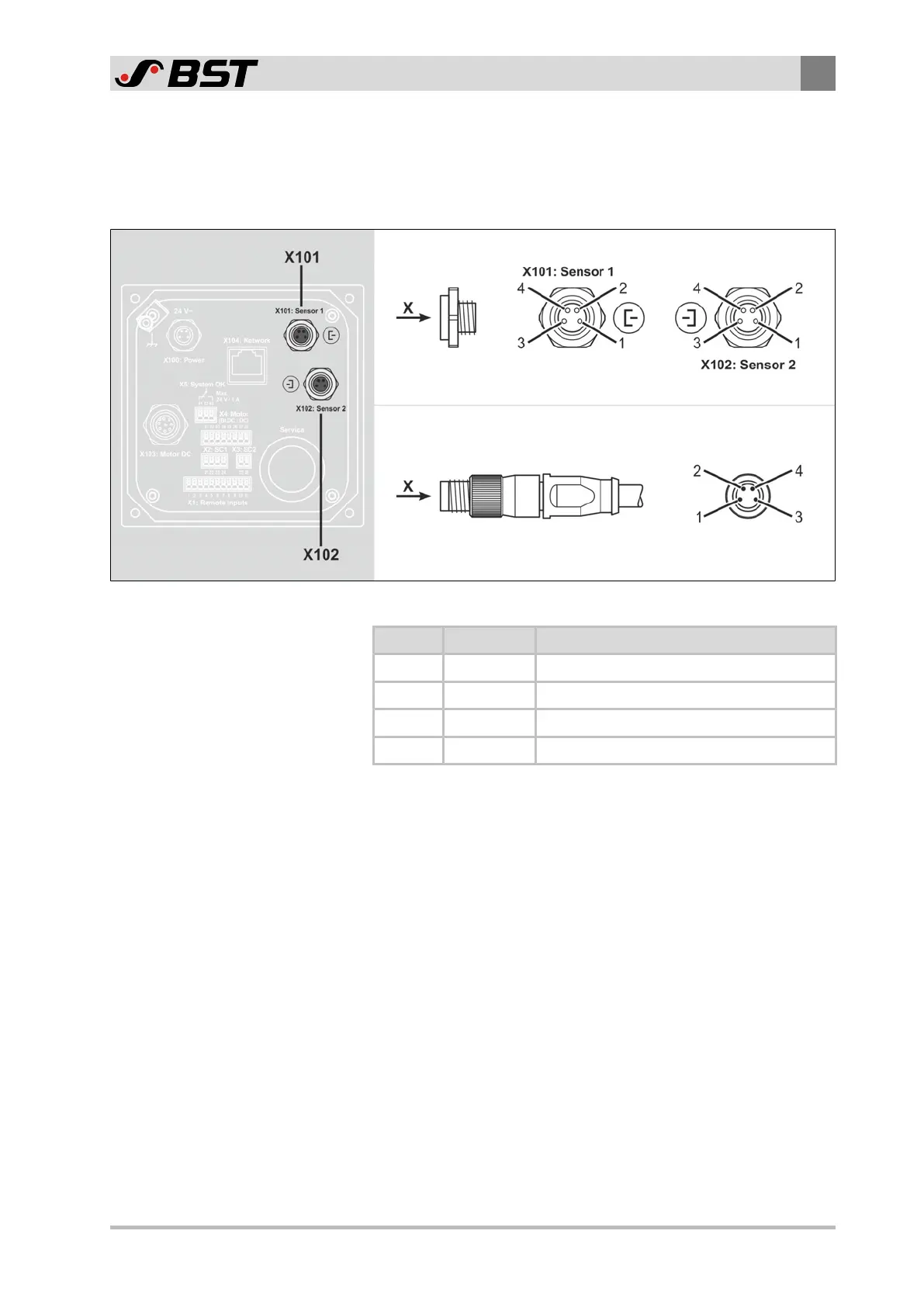
7.6.3 X101, X102 - CAN-Bus
The CAN-Bus participants (sensors, Drive Module 160, …) are
connected to the CAN-Bus interface of the controller via a 4-pin
micro-style connector M8.
View X
Connector (male)
Socket (female)
View X
Fig.16: Contact assignment of the plug connector
Contact Function Note
1 +24V Power supply +24V
2 CAN-H CAN high
3 CAN-GND Ground power supply
4 CAN-L CAN low

Table of Contents

Questions and Answers:

Question and Answer IconNeed help?

Do you have a question about the BST ekr CON 100 and is the answer not in the manual?

BST ekr CON 100 Specifications

General IconGeneral
BrandBST
Modelekr CON 100
CategoryController
LanguageEnglish

Related product manuals