Design and Function
3
ekr CON 100 – Installation and Operating Manual 23/130
3.7 Designation of the Sensors
You can connect two edge sensors and one line and contrast
sensor to the controller. In this operating manual, the sensors are
designated with Sensor 1, Sensor2 and Sensor3. In accordance
with the BST definition, the following assignment applies between
the sensors and the selector keys for the guiding mode:
Key Sensor assigned Control mode
Sensor 1 Left web edge
Sensor 2 Right web edge
Sensor 3 Line / contrast guiding
3.7.1 Edge Sensors (Sensor1/2)
For the installation position of the edge sensors (Sensor1/2), the
following applies:
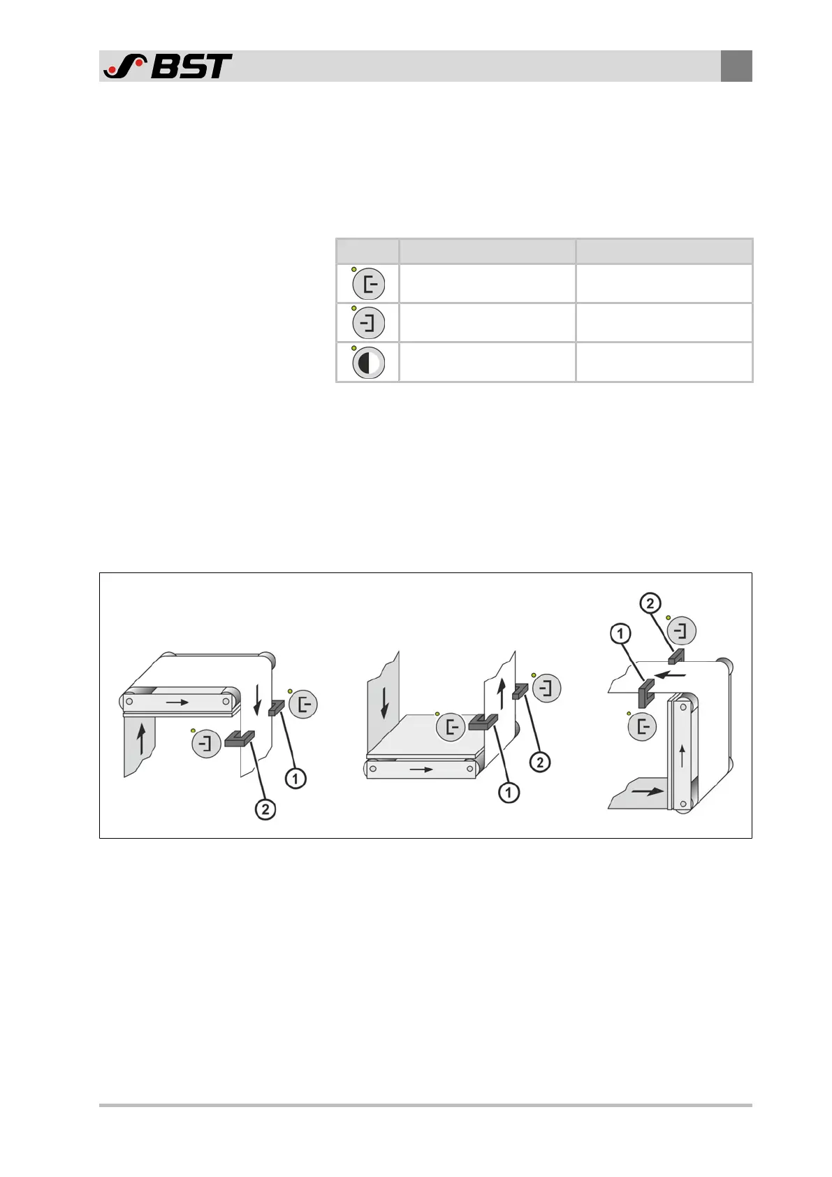
The sensor that is located on the left of the web in the web
running direction (viewed from the top of the material) is Sensor 1.
The top of the material is also the side of the web that has no
direct contact with the deflection pulleys of the guiding device.
Fig.4: Examples for the definition of Sensor ① and Sensor ②

 Loading...


